


Alteon OS Application Guide
Chapter 3: VLANs
8142C4911, January 2007
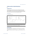
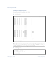
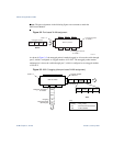
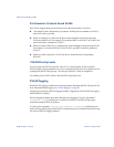
Figure 3-1 Default VLAN settings
NOTE – The port numbers specified in these illustrations may not directly correspond to the
physical port configuration of your switch model.
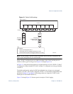
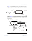
When a VLAN is configured, ports are added as members of the VLAN, and the ports are
defined as either tagged or untagged (see Figure 3-2 through Figure 3-5).
In Figure 3-1, untagged incoming packets are assigned directly to VLAN 2 (PVID = 2). Port 5
is configured as a tagged member of VLAN 2, and port 7 is configured as an untagged member
of VLAN 2.
The default configuration settings for GbE Switch Modules have all ports set as untagged
members of VLAN 1 with all ports configured as PVID = 1. In the default configuration exam-
ple shown in Figure 3-1 on page 81, all incoming packets are assigned to VLAN 1 by the
default port VLAN identifier (PVID =1).
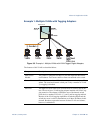
Figure 3-2 through Figure 3-5 illustrate generic examples of VLAN tagging.
Port 1
DA
SA
Data
CRC
Incoming
untagged
packet
BS45010A
Port 2 Port 3 Port 4 Port 5
VLAN 1
802.1Q Switch
By default:
Key
All ports are assigned PVID = 1
All external ports are untagged members of VLAN 1
All internal server ports are untagged members of VLAN 1
PVID = 1
Port 6 ...
DA
SA
Data
CRC
Outgoing
untagged packet
(unchanged)
Port 7