


Install the NT5D12 DDP 151
Procedure 16
Install the NT5D12 on Large Systems
Step Action
1
Determine the cabinet and shelf location where the NT5D12 card is
to be installed. The NT5D12 can be installed in any card slot in the
Network bus, subject to the cautionary note below.
CAUTION
Some installed-based systems can have a Bus
Terminating Unit (BTU) already installed. This can
interfere with a selected NT5D12 card location. In such
cases, the NT5D12 should be installed in an alternate
network bus card slot location.
2
Unpack and inspect circuit cards and cables.
3
If a DDCH is to be installed, refer to "NTBK51 DDCH installation
and removal" (page 91).
4
Set the option switches on the NT5D12 circuit card before
installation. Refer to "NTBK51 DDCH installation and removal"
(page 91).
S1 (faceplate switch) must be OFF (DIS) when installing the
NT5D12. S1 on the NT5D12 corresponds to the faceplate switch
on the QPC414 Network card.
5
Install the NT5D12 circuit card in the assigned shelf and slot.
6
Add related office administration data into the system memory.
7
If required, install the I/O adapters in the I/O panel.
8
Run and connect the NT5D12 cables.
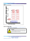
CAUTION
Clock Controller cables connecting the Clock Controller
and NT5D12 card must NOT be routed through the center
of the cabinet past the power harness. Instead, route
them around the outside of the equipment shelves.
9
If required, install connecting blocks at the MDF or wall mounted
crossconnect terminal.
10
If required, designate connecting blocks at the MDF or wall mounted
crossconnect terminal.
Nortel Communication Server 1000
ISDN Primary Rate Interface Installation and Commissioning
NN43001-301 02.03 Standard
Release 5.5 7 December 2007
Copyright © 2003-2007, Nortel Networks
.