


192 Echo canceller installation
•
Canceller only: OFF
•
H reset: OFF
•
H hold: OFF
PRI to Echo canceller pin assignments
The echo canceller is controlled by an RS-232 port on the PRI circuit pack.
The following tables give the echo canceller pin assignments, operating
parameters and initialization procedures.
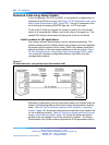
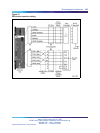
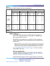
See Table 70 "PRI-to-Echo canceller - pin assignments" (page 192) for
PRI-to-Echo canceller pin assignments; refer to Figure 75 "PRI to echo
canceller cabling" (page 193) for a PRI-to-Echo-canceller cabling schematic.
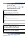
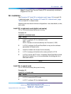
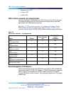
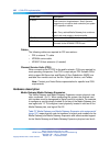
Table 70
PRI-to-Echo canceller - pin assignments
Signal PRI pin
Echo canceller
pin
EIA RS-232-C
circuit
designator
TXD
(Transmitted Data)
5
2
BA
RXD
(Received Data)
23
BB
RTS
(Request to Send)
—
4
CC
CTS
(Clear to Send)
—5
CB
Common Return
(signal ground)
10
7
AB
DCD
(received line signal detector)
18
CF
DTR
(data terminal ready)
420
CD
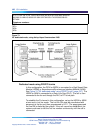
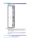
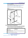
Electromagnetic Interference
The Electromagnetic Interference (EMI) filter assembly for PRI is PO643763.
The system meets FCC Part 15, Subpart J, Class A requirements regarding
EMI. In order to accomplish this, the SDI cables must exit the cabinet
through EMI filters on the I/O panel. This procedure depends on the system
cabinet type.
Nortel Communication Server 1000
ISDN Primary Rate Interface Installation and Commissioning
NN43001-301 02.03 Standard
Release 5.5 7 December 2007
Copyright © 2003-2007, Nortel Networks
.