


152 NT5D12 Dual-port DTI/PRI card installation
11
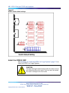
If required, install Network Channel Terminating Equipment (NCTE).
12
Enable faceplate switch S1. This is the "Loop Enable" switch.
The faceplate LEDs should go on for 4 seconds then go off and the
OOS, DIS and ACT LEDs should go on again and stay on.
IF DDCH is installed, the DCH LED should flash 3 times.
13
Run PRI/DTI Verification Test.
14 Run PRI status check.
—End—
Remove the NT5D12 DDP
Use Procedure 17 "Remove the NT5D12 DDP" (page 152) to remove the
NT5D12 from Large Systems.
CAUTION
A static discharge bracelet must be worn before handling circuit
cards. Failure to wear the bracelet can result in damage to the
circuit cards.
Procedure 17
Remove the NT5D12 DDP
Step Action
1
Determine the cabinet and shelf location of the NT5D12 card to
be removed.
2
Disable Network Loop using LD 60. The command is DISL "loop
number."
The associated DCHI might have to be disabled first. The faceplate
switch S1 should not be disabled until both PRI loops are disabled
first.
3
Remove data from memory, if the NT5D12 card is being completely
removed, not replaced.
4
Remove cross connections at the MDF to wall-mounted crossconnect
terminal.
5
Tag and disconnect cables from card.
6 Rearrange Clock Controller cables if required.
Nortel Communication Server 1000
ISDN Primary Rate Interface Installation and Commissioning
NN43001-301 02.03 Standard
Release 5.5 7 December 2007
Copyright © 2003-2007, Nortel Networks
.