


DTI software implementation 241
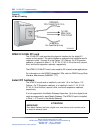
below the card slot holding the NTAK10 2.0 Mb DTI circuit card.
Reinstall the retaining bar to secure the cable(s).
2
Terminate the NTBK05DA/CA carrier cable as required.
—End—
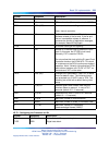
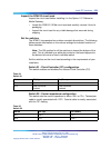
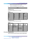
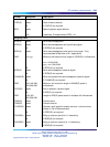
NTBK05DA pinouts
The pinouts for the NTBK05DA cable are as follows:
Table 88
NTBK05DA pinouts
Color Signal
pin 23 pin 6 Black R0
pin 48 pin 7 White T0
pin 50 pin 9 Bare R0/T0 FGND
pin 24 pin 2 Black R1
pin 49 pin 3 Red T1
pin 25 pin 5 Bare R1/T1 FGND
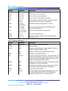
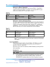
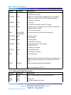
NTBK05CA pinouts
The pinouts for the NTBK05CA cable are as follows:
Table 89
NTBK05CA pinouts
From:
50-pin MDF
connector
To:
Transmit coax
connector
To:
Receive coax
connector
To:
50-pin MDF
connector
pin 23 Inner conductor
——
pin 48 outer conductor
——
pin 24
—
Inner conductor
—
pin 49
—
outer conductor
—
pin 21
——
pin 49
pin 46
——
pin 48
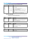
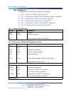
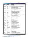
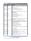
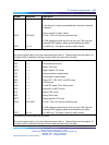
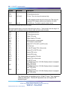
DTI software implementation
The following procedure describes the process required to program basic 2.0
Mb DTI on the system main and IP expansion cabinets or Media Gateway.
Nortel Communication Server 1000
ISDN Primary Rate Interface Installation and Commissioning
NN43001-301 02.03 Standard
Release 5.5 7 December 2007
Copyright © 2003-2007, Nortel Networks
.