


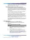
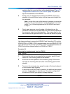

Install PRI hardware 207
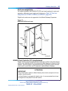
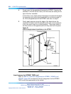
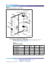
sockets, align the mounting holes on the daughterboard (Figure 79
"Daughterboard installation on the NTAK09" (page 208)) with the
tops of the standoffs on the NTAK09.
4
Slowly lower the daughterboard toward the NTAK09, keeping the
standoffs in line with all four holes, until the holes rest on top of the
four standoffs.
Note: If more than a very slight amount of pressure is required at
this point, the connector pins are not aligned with the connector
socket. If so, lift the daughterboard off the NTAK09 and return
to step 2.
5
Gently apply pressure along the edge of the board where the
connector is located until the standoffs at the two corners adjacent to
the connector snap into a locked position. Then press down on the
two corners on the opposite side until they also are locked into place.
—End—
Use these guidelines to remove the NTAK20 Clock Controller (CC) and the
NTAK93 DCHI or NTBK51 DDCH daughterboards from the NTAK09 DTI/PRI
card. Because of the physical layout of the mother and daughterboards, the
NTAK20 should be removed before the NTAK93 or NTBK51.
Procedure 28
Removing the daughterboards from the NTAK09
Step Action
1
Starting at the two corners opposite the connector, gently lift each
corner out of the locking groove of the standoff.
2
At the two corners adjacent to the connector, gently lift the entire
side until the mounting holes are clear of the locking groove of the
standoff.
3
To remove the connector pins, grasp the edge of the board adjacent
to the connector and lift gently.
If more than one NTAK09 card is installed, the additional cards might
not carry daughterboards, depending on the system configuration.
At least one NTAK20 (per system) is always required.
—End—
Nortel Communication Server 1000
ISDN Primary Rate Interface Installation and Commissioning
NN43001-301 02.03 Standard
Release 5.5 7 December 2007
Copyright © 2003-2007, Nortel Networks
.