


Installation procedures 169
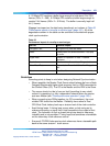
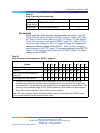
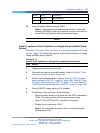
Table 64
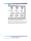
Clock Controller shelves and slots
System Shelf Slot(s)
Half Group,
Single Group
NT6D39 CPU/NET
9
Multi Group NTDA35 Network Module
13
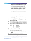
Set switches
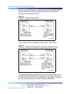
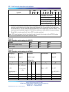
Before installing a clock controller, set the switches as shown in Table 65
"Clock Controller switch settings for QPC471 vintage H" (page 169), Table
66 "Clock Controller switch settings for QPC775" (page 170), and Table 67
"Clock Controller switch settings for NTRB53" (page 170). Table 65 "Clock
Controller switch settings for QPC471 vintage H" (page 169) displays the
settings for different vintages of the QPC471. Table 66 "Clock Controller
switch settings for QPC775" (page 170) shows the settings for the QPC775.
Table 67 "Clock Controller switch settings for NTRB53" (page 170) shows
settings for the NTRB53.
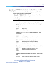
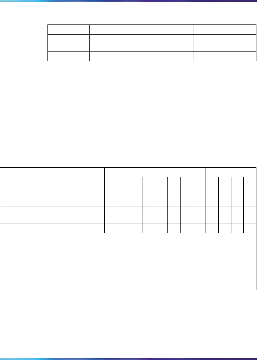
Table 65
Clock Controller switch settings for QPC471 vintage H
SW1 SW2 SW4
System 1 2 3 4 1 2 3 4 1 2 3 4
Half Group, Single Group
on on on on
off off off off off
on
**
Option 81 off off off off off off off off off
on
**
Multi Group (with the exception of
Option 81)
on
off off off off off off off **
on
**
Multi Group with Fiber Network
on
off off off off off off off **
on
**
* If there is only one clock controller card in the system, set to OFF. If there are two clock
controller cards, determine the total cable length between the J3 connectors (no single cable
can exceed 25 ft.) and set these two switch positions for this cable length, as shown above. The
maximum total (combined) length is 50 ft. Set the switches on both cards to the same settings.
** Set to ON for clock controller 0. Set to OFF for clock controller 1.
Note: FNF based-systems the total clock path length is equal to the length of the NTRC49 cable
used to connect between the two clock controller cards.
Nortel Communication Server 1000
ISDN Primary Rate Interface Installation and Commissioning
NN43001-301 02.03 Standard
Release 5.5 7 December 2007
Copyright © 2003-2007, Nortel Networks
.