


NT5D97 Dual-port DTI2/PRI2 card 37
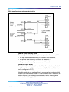
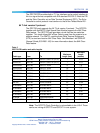
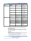
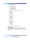
Function
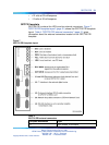
Faceplate
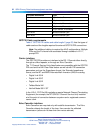
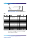
Designator Type Description
Unit 0 Clock 0 RJ11 Connector Connects reference
clock 0 to Clock
Controller card 0
Unit 0 Clock 1 RJ11 Connector Connects reference
clock 0 to Clock
Controller card 1
Unit 1 Clock 0 RJ11 Connector Connects reference
clock 1 to Clock
Controller card 0
Unit 1 Clock 1 RJ11 Connector Connects reference
clock 1 to Clock
Controller card 1
J5 TRK 9 Pin
Female D Connector
Two external E1 Trunk
0 and Trunk 1
Connectors
J6 DCH 26 Pin
Female D Connector
Connects to external
DCH or MSDL
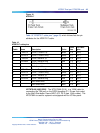
ENET 2 Red LEDs ENET 0 or ENET 1 is
disabled
DIS 2 Red LEDs Trunk 0 or Trunk 1 is
disabled
OOS 2 Yellow LEDs Trunk is out of service
NEA 2 Yellow LEDs Local (Near End) Alarm
FEA 2 Yellow LEDs Far End Alarm
LBK 2 Yellow LEDs Loop Back test being
performed on Trunk 0
or Trunk 1
LEDs
DCH Bicolor Red/Green LED NTBK51AA status
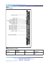
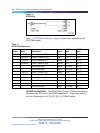
The following is a brief description of each element on the faceplate.
Enable/Disable Switch
This switch is used to disable the card pr ior to insertion or removal from
the network shelf. While this switch is in disable position, the card will not
respond to the system CPU.
ENET LEDs
Two red LEDs indicate if the "ENET0" and "ENET1" portions of the card are
disabled. These LEDs are lit in the following cases:
•
When the enable/disable switch is in disabled state (lit by hardware).
•
After power-up, before the card is enabled.
Nortel Communication Server 1000
ISDN Primary Rate Interface Installation and Commissioning
NN43001-301 02.03 Standard
Release 5.5 7 December 2007
Copyright © 2003-2007, Nortel Networks
.