


Configuring and managing IP interfaces and services 191
Nortel WLAN—Security Switch 2300 Series Configuration Guide
Tracing a route
You can trace the router hops necessary to reach an IP host.
The traceroute facility uses the TTL (Time to Live) field in the IP header to cause routers and servers to generate specific
return messages. Traceroute starts by sending a UDP datagram to the destination host with the TTL field set to 1. If a
router finds a TTL value of 1 or 0, it drops the datagram and sends back an ICMP Time Exceeded message to the sender.
The traceroute facility determines the address of the first hop by examining the source address field of the ICMP
time-exceeded message.
To identify the next hop, traceroute again sends a UDP packet, but this time with a TTL value of 2. The first router
decrements the TTL field by 1 and sends the datagram to the next router. The second router sees a TTL value of 1,
discards the datagram, and returns the Time Exceeded message to the source. This process continues until the TTL is
incremented to a value large enough for the datagram to reach the destination host (or until the maximum TTL is
reached).
To determine when a datagram has reached its destination, traceroute sets the UDP destination port in the datagram to a
very large value, one that the destination host is unlikely to be using. In addition, when a host receives a datagram with
an unrecognized port number, it sends an ICMP Port Unreachable error to the source. This message indicates to the
traceroute facility that it has reached the destination.
To trace a route to a destination subnet, use the following command:
traceroute host [dnf] [no-dns] [port port-num] [queries num] [size size] [ttl hops] [wait ms]
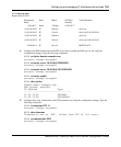
To trace the route to host server1, type the following command:
WSS# traceroute server1
traceroute to server1.example.com (192.168.22.7), 30 hops max, 38 byte packets
1 engineering-1.example.com (192.168.192.206) 2 ms 1 ms 1 ms
2 engineering-2.example.com (192.168.196.204) 2 ms 3 ms 2 ms
3 gateway_a.example.com (192.168.1.201) 6 ms 3 ms 3 ms
4 server1.example.com (192.168.22.7) 3 ms * 2 ms
In this example, server1 is four hops away. The hops are listed in order, beginning with the hop that is closest to the
WSS and ending with the route’s destination. (For information about the command options, see the Nortel WLAN
Security Switch 2300 Series Command Line Reference.)
IP interfaces and services configuration scenario
This scenario configures IP interfaces, assigns one of the interfaces to be the system IP address, and configures a default
route, DNS parameters, and time and date parameters.
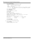
1 Configure IP interfaces on the wss_mgmt and roaming VLANs, and verify the configuration changes.
Type the following commands:
WSS# set interface wss_mgmt ip 10.10.10.10/24
success: change accepted.
WSS# set interface roaming ip 10.20.10.10/24
success: change accepted.