


3.0 HARDWARE CONNECTIONS
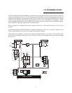
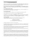
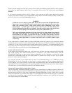
3.1 CONNECTOR PIN DIAGRAM
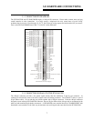
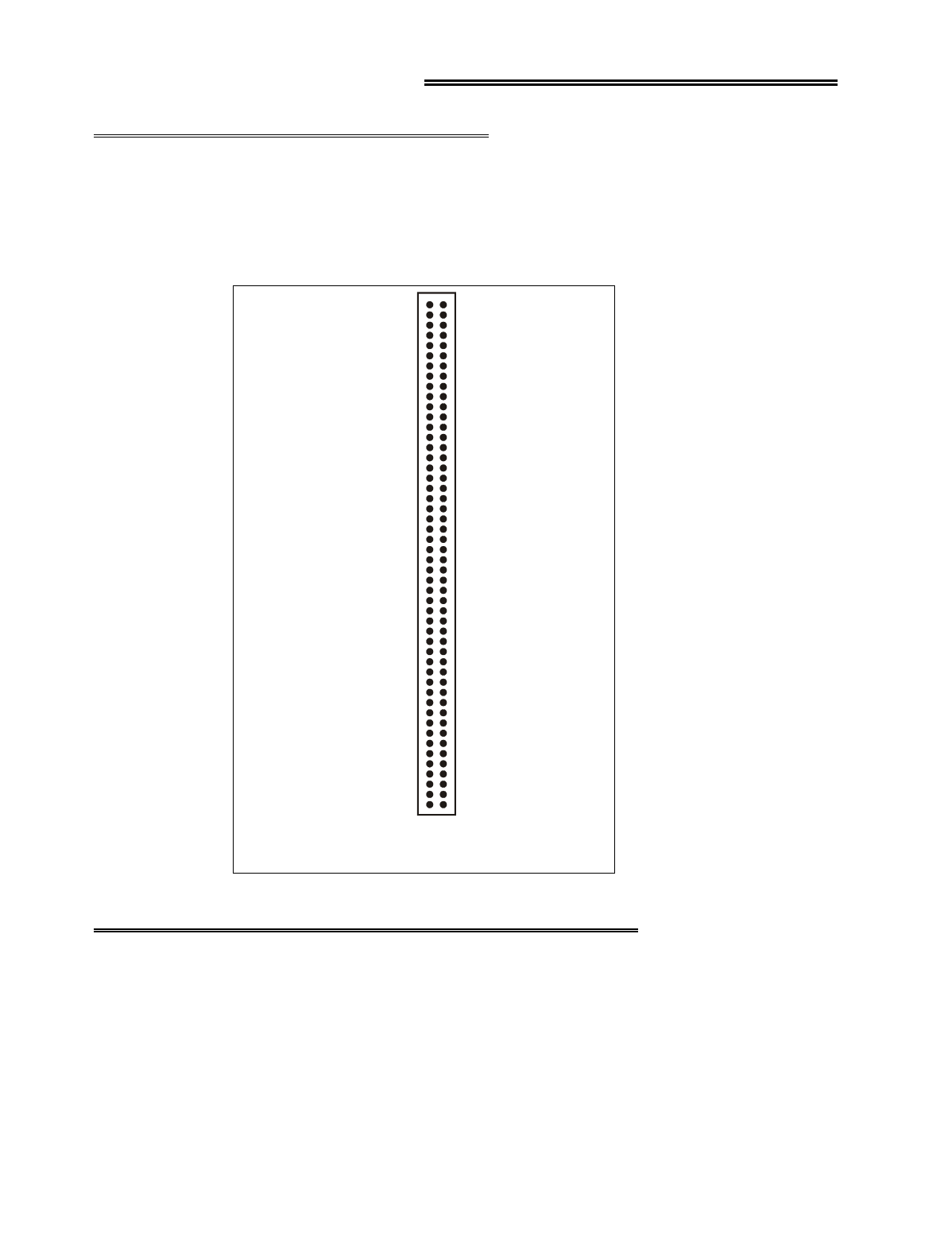
The PCI-DAS1200 and PCI-DAS1200/JR employ a 100-pin I/O connector. Please make accurate notes and pay
careful attention to wire connections. In a large system, a misplaced wire may create hours of work ‘fixing’
problems that do not exist. Note that pins 35, 36, 37, and 38 are for analog outputs and are therefore NC (no connec-
tion) on the PCI-DAS1200/JR board. (Pin 77 is also NC on the /JR board).
Analog Ground 1
Analog Input Ch 0 High 2
Analog Input Ch 0 Low / 8 High 3
4
5
6
7
8
9
10
11
12
13
14
15
16
17
Analog Ground 18
NC 19
20
21
22
23
24
25
26
27
28
29
30
31
32
33
34
CLK 4 39
GATE 4 40
OUT 4 41
A/D External Pacer 42
NC 43
NC 44
A/D External Trigger 45
46
47
PC +5V 48
NC 49
PC Ground 50
Analog Input Ch 1 High
Analog Input Ch 1 Low / 9 High
Analog Input Ch 2 High
Analog Input Ch 2 Low / 10 High
Analog Input Ch 3 High
Analog Input Ch 3 Low / 11 High
Analog Input Ch 4 High
Analog Input Ch 4 Low / 12 High
Analog Input Ch 5 High
Analog Input Ch 5 Low / 13 High
Analog Input Ch 6High
Analog Input Ch 6 Low / 14 High
Analog Input Ch 7 High
Analog Input Ch 7 Low / 15 High
NC
NC
NC
NC
NC
NC
NC
NC
NC
NC
NC
NC
NC
NC
NC
D/A GND 0 35
D/A OUT 0 36
D/A GND 1 37
D/A OUT 1 38
NC
NC
51 Digital A0
52
53
54
55
56
57
58
59
60
61
62
63
64
65
66
67
68
69
70
71
72
73
74
75 NC
76
77
78
79
80
81
82
83
84
85
86
87
88
89
90 PC +12V
91 PC Ground
92 PC -12V
93
94
95 A/D Internal Pacer Output
96
97
98
99 NC
100 PC Ground
Digital A1
Digital A2
Digital A3
Digital A4
Digital A5
Digital A6
Digital A7
Digital B0
Digital B1
Digital B2
Digital B3
Digital B4
Digital B5
Digital B6
Digital B7
Digital C0
Digital C1
Digital C2
Digital C3
Digital C4
Digital C5
Digital C6
Digital C7
NC
10 MHz OUT
NC
NC
CLK 6
GATE 6
OUT 6
NC
NC
CLK 5
GATE 5
OUT 5
NC
PC Ground
NC
NC
NC
NC
NC
PCI-DAS1200 Connector Diagram
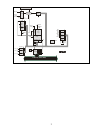
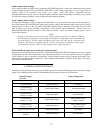
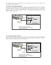
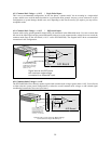
3.2 CONNECTING SIGNALS TO THE PCI-DAS1200
The 100-pin connector provides a far greater signal density than the traditional 37-pin D type connector. In
exchange for that density comes a far more complex cable and mating connector. The C100-FF-2 cable is a pair of
50-pin ribbon cables. At one end they are joined together with a 100-pin connector. From the 100-pin connector
designed to mate with the PCI-DAS1200 connector, the two 50-pin ribbon cables diverge and are terminated at the
other end with standard 50-pin header connectors. A CIO-MINI50 screw terminal board (or CIO-MINI50/DST with
detachable screw terminals) is the ideal way to terminate real-world signals and route them into the PCI-DAS1200.
7