


7.5 BADR3
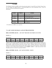
The I/O Region defined by BADR3 contains data and control registers for the ADC Pacer, Pre/Post-Trigger Count-
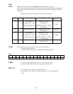
ers, User Counters and Digital I/O bytes. The PCI-DAS1200 has two 8254 counter/timer devices. These are
referred to as 8254A and 8254B and are assigned as
shown below:
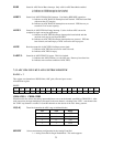
User Counter #528254B
User Counter #418254B
User Counter #3 & ADC Pre-Trigger Index
Counter
08254B
ADC Pacer Upper Divider28254A
ADC Pacer Lower Divider18254A
ADC Post-Trigger Sample Counter08254A
FunctionCounter #Device
All reads/writes to BADR3 are byte operations.
7.5.1 ADC PACER CLOCK DATA AND CONTROL REGISTERS
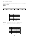
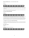
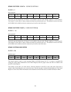
8254A COUNTER 0 DATA -
ADC POST TRIGGER CONVERSION COUNTER
BADR3 + 0
READ/WRITE
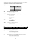
D0D1D2D3D4D5D6D7
01324567
Counter 0 is used to stop the acquisition when the desired number of samples have been gathered. It essentially is
gated on when a 'residual' number of conversions remain. The main counting of samples is done by the Interrupt
Service Routine, which will increment each time by 'packets' equal to 1/2 FIFO. Generally the value loaded into
Counter 0 is N mod 1024, where N is the total count, or the post trigger count, since Total count is not known when
pre-trigger is active. Counter 0 will be enabled by use of the
ARM
bit (BADR1 + 4) when the next-to-last 1/2-full
interrupt is processed. Counter 0 is to operated in Mode 0.
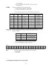
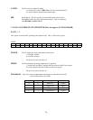
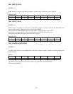
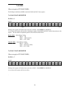
8254A COUNTER 1 DATA
- ADC PACER DIVIDER LOWER
BADR3 + 1
READ/WRITE
D0D1D2D3D4D5D6D7
01324567
28