


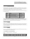
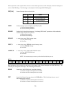
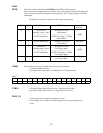

ARM,
FFM0
These bits work in conjunction with
PRTRG
during FIFO'd ADC operations.
Direct register level programming is beyond the scope of this manual, and should be attempted
only by extremely experienced register level programmers. Call Technical Support for further
information.
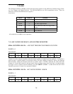
The table below provides a summary of bit settings and operation.
XTRIG
# Samples <1/2 FIFO,
Pre-Trigger Mode
Via SW immediately
11
ADHF
# Samples >1 FIFO
Pre-Trigger Mode
----------------------------------
1/2 FIFO < # Samples < 1 FIFO
Pre-Trigger Mode
Via SW when
remaining count <1024
------------------------
Via SW immediately
01
ADC Pacer
# Samples <1/2 FIFO
Normal Mode
Via SW immediately
10
ADHF
# Samples >1 FIFO
Normal Mode
----------------------------------
1/2 FIFO < # Samples < 1 FIFO
Normal Mode
Via SW when
remaining count <1024
------------------------
Via SW immediately
00
Sample CTR
Starts on...
FIFO ModeARM
is set...
FFM0PRTRG
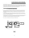
C0SRC
This bit allows the user to select the clock source for user Counter 0.
1 = Internal 10MHz oscillator
0 = External clock source input via CTR0CLK pin on 100p connector.
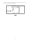
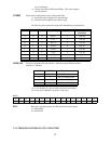
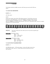
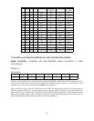
READ
-------XTRIG----INDX_GT---
0123456789101112131415
XTRIG
1 = External Trigger flip-flop has been set. This bit is write-cleared.
0 = External Trigger flip-flop reset. No trigger has been received.
INDX_GT
1 = Pre-trigger index counter has completed its count.
0 = Pre-trigger index counter has not been gated on or has not yet completed its
count
.
24