


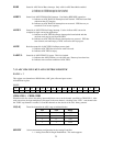
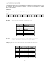
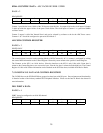
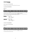

8254A COUNTER 2 DATA - ADC PACER DIVIDER UPPER
BASE + 2
READ/WRITE
D0D1D2D3D4D5D6D7
01324567
Counter 1 provides the lower 16 bits of the 32-bit pacer clock divider. Its output is fed to the clock input of Counter
2 which provides the upper 16-bits of the pacer clock divider. The clock input to Counter 1 is a precision 10MHz
oscillator source.
Counter 2 output is called the 'Internal Pacer' and can be selected by software to the be the ADC Pacer source.
Counters 1 & 2 should be configured to operate in 8254 Mode 2.
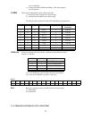
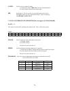
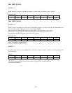
ADC 8254 CONTROL REGISTER
BADR3 + 3
WRITE ONLY
D0D1D2D3D4D5D6D7
01324567
The control register is used to set the operating Modes of 8254 Counters 0,1 & 2. A counter is configured by writing
the correct Mode information to the Control Register followed by count written to the specific Counter Register.
The Counters on the 8254 are 16-bit devices. Since the interface to the 8254 is only 8-bits wide, Count data is
written to the Counter Register as two successive bytes. First the low byte is written, then the high byte. The Control
Register is 8-bits wide. Further information can be obtained on the 8254 data sheet, available from Intel or Harris.
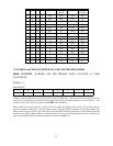
7.5.2 DIGITAL I/O DATA AND CONTROL REGISTERS
The 24 DIO lines on the PCI-DAS1200 are grouped as three byte-wide I/O ports. Port assignment and functionality
is identical to that of the industry standard 8255 Peripheral Interface. Please see the Intel or Harris data sheets for
more information.
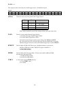
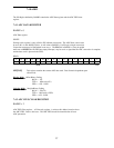
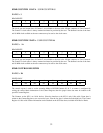
DIO PORT A DATA
BADR3 + 4
PORT A may be configured as an 8-bit I/O channel.
READ/WRITE
D0D1D2D3D4D5D6D7
01324567
29