


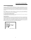
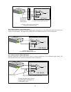

Small Common Mode Voltages
If the voltage between the signal source ground and PCI-DAS1200 ground is small, the combination of the ground
voltage and input signal will not exceed the PCI-DAS1200’s +/-10V common mode range, (i.e., the voltage between
grounds, added to the maximum input voltage, stays within +/-10V), This input is compatible with the
PCI-DAS1200 and the system may be connected without additional signal conditioning. Fortunately, most systems
will fall in this category and have a small voltage differential between grounds.
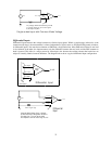
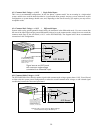
Large Common Mode Voltages
If the ground differential is large enough, the PCI-DAS1200’s +/- 10V common mode range will be exceeded (i.e.
the voltage between PCI-DAS1200 and signal source grounds, added to the maximum input voltage you’re trying to
measure exceeds +/-10V). In this case the PCI-DAS1200 cannot be directly connected to the signal source. You will
need to change your system grounding configuration or add isolation signal conditioning. (Please look at our
ISO-RACK and ISO-5B-series products to add electrical isolation, or give our technical support group a call to
discuss other options.)
NOTE
Relying on the earth prong of a 120 Vac for signal ground connections is not advised.. Different
ground plugs may have large and potentially even dangerous voltage differentials. Remember that
the ground pins on 120 Vac outlets on different sides of the room may only be connected in the
basement. This leaves the possibility that the “ground” pins may have a significant voltage differ-
ential (especially if the two 120 Vac outlets happen to be on different phases!)
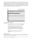
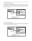
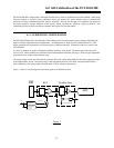
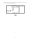
PCI-DAS1200 and signal source already have isolated grounds
Some signal sources will already be electrically isolated from the PCI-DAS1200. The diagram below shows a typical
isolated ground system. These signal sources are often battery powered, or are fairly expensive pieces of equipment
(since isolation is not an inexpensive proposition), isolated ground systems provide excellent performance, but
require some extra effort during connections to ensure optimum performance is obtained. Please refer to the follow-
ing sections for further details.
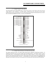
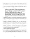
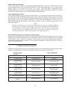
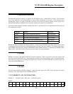
4.2 WIRING CONFIGURATIONS
Combining all the grounding and input type possibilities provides us with the following potential connection configu-
rations. The combinations along with our recommendations on usage are shown in the chart below.
Ground Category Input Configuration
Our view
RecommendedDifferential Inputs
Already Isolated
Grounds
AcceptableSingle-ended InputsAlready Isolated Grounds
Unacceptable without
adding Isolation
Differential Inputs
Common Mode
Voltage > +/-10V
Unacceptable without
adding Isolation
Single-Ended Inputs
Common Mode
Voltage > +/- 10V
RecommendedDifferential Inputs
Common Mode
Voltage < +/-10V
Not RecommendedSingle-Ended Inputs
Common Mode
Voltage < +/-10V
AcceptableDifferential InputsCommon Ground
RecommendedSingle-Ended InputsCommon Ground
12