


2.1.3 Using InstaCal
InstaCal is the Installation, Calibration and Test software supplied with all I/O boards.
If InstaCal finds that a new PCI board has been installed and is not in the configuration file (cb.cfg) a dialog will
appear listing any PCI boards that InstaCal has detected in the system. Each board in the list may
be checked or unchecked. Those boards in the list that are checked will be added to the configuration file and appear
in the InstaCal’s board list view.
InstaCal help is available by pressing the F1 function key. Most of InstaCal is intuitively obvious, and for that
reason there is no user's manual for InstaCal.
The base address and IRQ are allocated by the PC’s PCI plug & play software, and may not be modified through
InstaCal. If you have installed ISA bus boards in the past, you are familiar with the need to select a base address and
interrupt level. On PCI systems this is not of concern to you. The operating system and installation software
automatically selects the base address and IRQ, and ensures that it does not conflict with other installed boards.
Additional board options that are automatically set, may be configured by selecting the Board Configuration menu in
InstaCal This option will display the available board configuration parameters as well as the address and IRQ
already assigned to the board. All board information is stored in the configuration file CB.CFG. This file is accessed
by the Universal Library for programmers. Note also that the Universal Library is the I/O board interface for
packaged applications such as Labtech Notebook and HP-VEE, therefore the InstaCal settings must be made in order
for these and other applications to run.
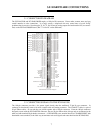
The board's base address is also stored in the system software. Once InstaCal installation software is run, other
programming methods such as direct IN and OUT statements can write and read the PCI board registers by reference
to the base address and the offset from base address corresponding to the chart of registers located elsewhere in this
manual.
But a word of warning is in order here. Direct writes to the addresses simply by reference to the base address of the
PCI board I/O registers is not advised. Since the addresses assigned by the PCI plug & play software are not under
your control, there is no way to guarantee that your program will run in any other computer. Not only that, when you
install new systems or components in your computer, previous base address assignments may be changed, and any
particular board may be moved. It is best to use a library such as Universal Library or a program such as HP-VEE to
make measurements with your PCI board.
2.1.4 Testing the Installation
After you have run the install program and set your base address with InstaCal, it is time to test the installation. The
following section describes the InstaCal procedure to test that your board is properly installed.
With InstaCal running, choose the TEST item on the main menu.
a.
Select the board you just installed from InstaCal’s board list view.
b.
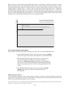
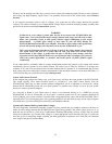
Select the option Test/Analog to perform a board loop back test. This test will exercise the various functions
of the board by simply connecting one of the board’s output signals to one of the board’s input channels.
c.
Select an input channel and signal source to test.
d.
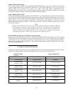
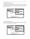
Complete the connections shown in the dialog box and verify that the indicated waveform is displayed in
the plot window.
e.
The “I/O Test Menu” lists the option “Plot”, select it and make the connections as shown to test your card.
4