


4.2.3 Common Mode Voltage < +/-10V / Single-Ended Inputs
This is not a recommended configuration. In fact, the phrase “common mode” has no meaning in a single-ended
system, and this case would be better described as a system with offset grounds. Anyway, you are welcome to try this
configuration, no system damage should occur, and, depending on the overall accuracy you require, you may receive
acceptable results.
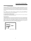
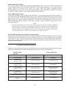
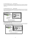
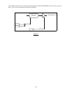
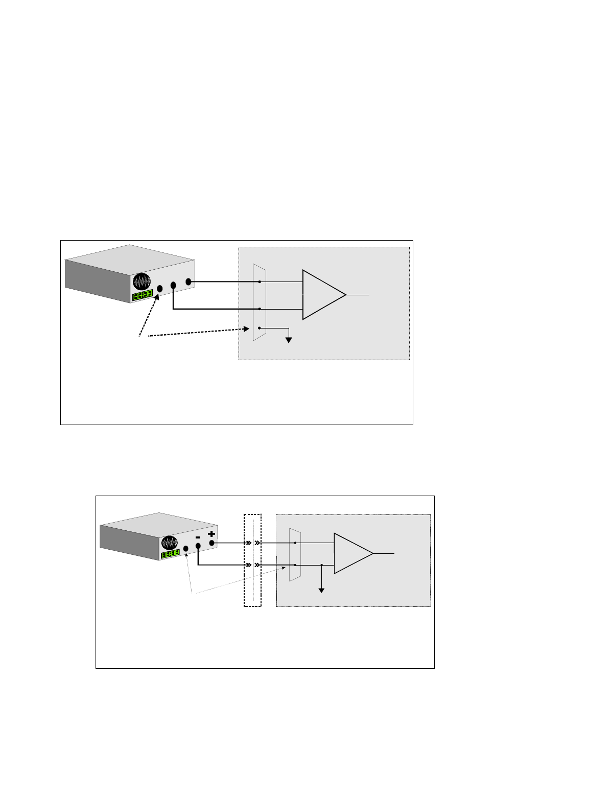
4.2.4 Common Mode Voltage < +/-10V / Differential Inputs
Systems with varying ground potentials should always be monitored in the differential mode. Use care to ensure that
the sum of the input signal and the ground differential (referred to as the common mode voltage) does not exceed the
common mode range of the A/D board (+/-10 V on the PCI-DAS1200). The diagram below shows recommended
connections in this configuration.
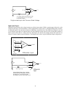
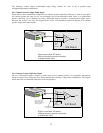
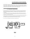
4.2.5 Common Mode Voltage > +/-10V
The PCI-DAS1200 will not directly monitor signals with common mode voltages greater than +/-10V. You will need
to either alter the system ground configuration to reduce the overall common mode voltage, or add isolated signal
conditioning between the source and your board.
14
+
-
Input
Amp
To A/D
A/D Board
I/O
Connector
LL GND
CH High
CH Low
Signal Source
with Common
Mode Voltage
Si
g
nal source and A/D board
with common mode volta
g
e
connected to a differential input.
GND
The voltage differential
between these grounds,
added to the maximum
input signal must stay
within +/-10V
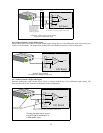
System with a Lar
g
e Common Mode Volta
g
e,
Connected to a Sin
g
le-Ended Input
I/O
Connector
+
-
Input
Amp
To A/D
LL GND
CH IN
A/D Board
L
arge common
mode voltage
between signal
source & A/D board
GND
Isolation
Barrier
When the volta
g
e difference
between si
g
nal source and
A/D board
g
round is lar
g
e
enou
g
h so the A/D board’s
common mode ran
g
e is
exceeded, isolated si
g
nal
conditionin
g
must be added.