


10
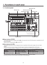
1. Functions in each area
1-3. Wipe area
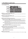
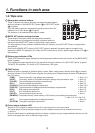
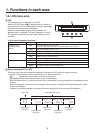
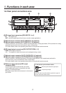
8 Wipe pattern selector buttons
These 12 buttons are used to select the corresponding wipe patterns
while the indicator of the [BKGD PATT] button (9) or [KEY PATT] button
(9) is lighted.
They are used to select the corresponding setting menus when the
indicator of the FUNC button (;) is lighted.
The indicator of the selected button lights in amber.
BKGD PATT
KEY PATT
FUNC
WIPE PATTERN / FUNCTION
ON
WIPE SQ
SL 3D
PAGE
TIME WIPE COLOR
KEY CHR KEY FREEZE
DSK PinP IN/OUT
MEMORY XPT SYSTEM
1 2 3
4 5 6
7 8 9
10 12
11
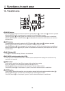
9 BKGD, KEY pattern selector buttons
These buttons are used to switch the wipe pattern selection.
The wipe pattern of a background transition is selected when the
indicator of the [BKGD PATT] button is lighted after it was pressed.
The wipe pattern of a key transition is selected when the indicator of the [KEY PATT] button is lighted after it
was pressed.
Each time the [BKGD PATT] button or [KEY PATT] button is pressed, the pattern page is changed in the
sequence of WIPE, SQ (squeeze), SL (slide) and 3D (3 dimensions), and the pattern page indicator LED (:) is
also switched.
: Pattern page indicator LEDs
These LEDs indicate the pages selected by the background transitions while the indicator of the [BKGD PATT]
button is lighted.
They indicate the pages selected by the key transitions while the indicator of the [KEY PATT] button is lighted.
The WIPE, SQ (squeeze), SL (slide) or 3D (3 dimensions) LED lights.
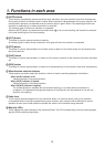
; FUNC button
When this button is pressed, its indicator lights in amber. When a wipe pattern selector button (8) is pressed
while the indicator of the [FUNC] button is lighted, the setting menu indicated below the button is displayed on
the LCD screen.
[TIME]:
The auto transition time settings are performed. See 3-1-5.
[WIPE]:
The modify, border or soft effect decoration settings are performed for wipe. See 3-2.
[COLOR]:
The color background settings are performed. See 3-7.
[KEY]:
The key settings are performed. See 3-3.
[CHR KEY]:
The chroma key settings are performed. See 3-3-6.
[FREEZE]:
The freeze status is displayed and freeze settings are performed. See 3-8.
[DSK]:
DSK settings are performed. See 3-5.
[PinP]:
PinP settings are performed. See 3-4.
[IN/OUT]:
The input/output signals are set. See 4.
[MEMORY]:
The preset memory, frame memory or SD memory card settings are performed.
See 3-10, 3-11 and 3-12.
[XPT]:
The crosspoint assignment is displayed and set. See 5-2.
[SYSTEM]:
The system settings are performed. See 5.
< Freeze status indicator LED
When this LED is lighted, it means that one of the input signals is in the freeze status.
The freeze status of the input signals assigned to the crosspoint buttons can be checked on the menu.
See 3-8.
Since the freeze status is established while this indicator is lighted, the input image handled inside the unit will
remain unchanged even when a different image is input.