


17
1. Functions in each area
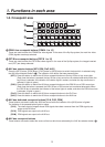
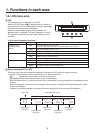
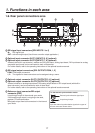
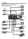
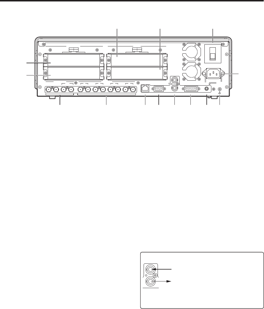
1-9. Rear panel connections area
POWER
1
REF
SLOT2
2
SLOT
4
2
34 SLOT1
1
SLOT2 8
~IN
SDI INPUTS
TALLY
6
6
INPUTS
SDI OUTPUTS
INOUT
3
INOUT
2
INOUT
1
INOUT
OUTPUTS
1
5 7
SLOT
OFF
2
SLOT1 5
SLOTSLOT
PGM
RS-422LAN
ON
ANALOG INPUTS
Y Pb
Pr
Y Pb
Pr
DVI INPUTS
ANALOG OUTPUTS
Y Pb
Pr
Y Pb
Pr
DVI/ANALOG OUTPUTS
Y Pb
Pr
DVI-I
DVI-I DVI-I
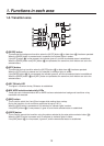
GPI
SIGNAL
GND
R SDI signal input connectors [SDI INPUTS 1 to 4]
IN: SDI signal input
OUT: activ
e through output (Use this as a monitor output application.)
S Optional input connector SLOT1 [INPUTS 5, 6] (optional)
T Optional input connector SLOT2 [INPUTS 7, 8] (optional)
A board (with built-in up-converter), whether an SDI input board, analog input board, DVI input board or analog
composite input board, can be connected to each of these slots.
For further details, refer to the operating instructions of the optional board concerned.
U SDI signal output connectors [SDI OUTPUTS PGM, 1, 2]
PGM: PGM output connectors
1, 2: The signals f
or these connectors can be assigned using a menu.
V Optional output connector SLOT1 [OUTPUTS 3, 4] (optional)
W Optional output connector SLOT2 [OUTPUTS 5, 6] (optional)
A board, whether an analog output board, DVI/analog output board or SDI output board (with built-in
down-converter), can be connected to each of these slots.
For further details, refer to the operating instructions of the optional board concerned.
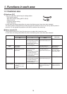
X Reference input connector/BB output
connector [REF]
Loop-through output in the external sync mode.
If the loop-through output is not going to be used,
provide a 75-ohm termination.
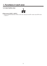
BB signals output from both connectors in the internal
sync mode.
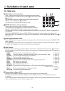
<In the external synchronization mode>
External synchronization signal input
Loop-through output
REF
Input the external synchronization signal to the upper of
the two connectors shown above.