


92
5. System settings
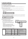
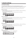
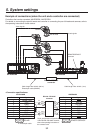
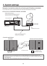
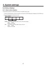
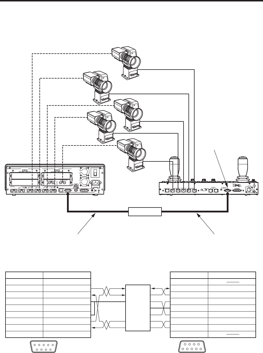
Example of connections (when the unit and a controller are connected)
Controllers that can be connected: AW-RP655N, AW-RP555N
For details on connecting the pan-tilt heads and controller or connecting the pan-tilt heads and cameras, refer to
the operating instructions of each device.
POWER
1
REF
GPI
SLOT2
2
SLOT
4
2
34 SLOT1
1
SLOT2 8
~IN
SDI INPUTS
TALLY
6
6
INPUTS
SIGNAL
SDI OUTPUTS
GND
INOUT
3
INOUT
2
INOUT
1
INOUT
OUTPUTS
1
5 7
SLOT
OFF
2
SLOT1 5
SLOTSLOT
PGM
RS-422LAN
ON
ANALOG INPUTS
Y Pb
Pr
Y Pb
Pr
DVI INPUTS
ANALOG OUTPUTS
Y Pb
Pr
Y Pb
Pr
DVI/ANALOG OUTPUTS
Y Pb
Pr
DVI-I
DVI-I DVI-I
INOUT
SDI INPUTS
INOUT
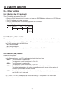
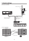
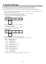
Camera
Pan-tilt head
REMOTE/SERVICE
connector
Video signals
Control signals
Cable length: Max. 32.8 ft. (10 m)Cable length: Max. 656 ft. (200 m)
Twisted pair cable (AWG24)
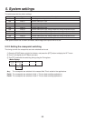
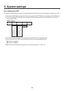
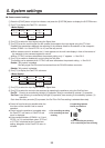
RS-422RS-232C
converter
AW-RP655NAV-HS400AN
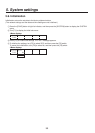
<Connection specifications>
TXD –
RXD –
RXD +
GND
TXD +
CTS
RXD
TXD
DTR
RTS
DSR
GND
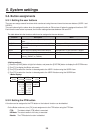
1 FRAME GND
2 TXD –
3 RXD +
4 GND
5
6 GND
7 TXD +
8 RXD –
9 FRAME GND
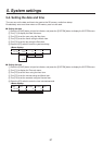
NC
1
2 RXD IN
3 TXD OUT
4 DTR
5
6 DSR
7 RTS
8 CTS
9
GND
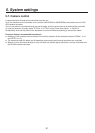
RS-422 REMOTE/SERVICE
12345
9 8 7 6
51
9
6
RS-422RS-232C
converter
Pin No. Signal Pin No. Signal
AV-HS400AN AW-RP655N
For pin assignments and specifications
of the RS-422RS-232C converter,
refer to the operating instructions of
the converter used.
: Twisted pair cable