


38
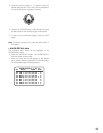
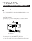
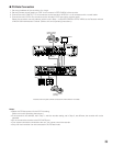
● To Control a Recorder and Cameras via the Network
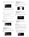
The following is the description of the connection between a recorder and this unit to control the recorder and cameras via the
network.
1. Set the unit address of the recorder to 5 or larger.
(Refer to the recorder’s operating instructions.)
2. Set the [Camera control] setting to “PSD” for all cameras in SETUP MENU of the recorder.
3. Connect the unit’s CAM OUT 1 to 16 connectors to the recorder’s VIDEO IN 1 to 16 connectors with a coaxial cable.
4. Connect the unit’s EXT IN connector to the recorder’s MULTISCREEN OUT connector with a coaxial cable.
5. Connect the unit’s DATA HDR and DATA4 connectors to the recorder’s DATA ports with modular cables.
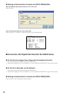
6. Select the recorder’s new unit address, which is set in Step 1, in 600 RECORDER of SETUP MENU or the Recorder window
of WJ-SX150A Administrator Console. (Refer to this unit’s operating instructions.)
Notes:
• Select the PS·Data protocol for the DATA 4 setting.
(Refer to this unit’s operating instructions.)
• If the recorder’s unit address, set in Step 1, and the recorder setting, set in Step 6, are different, the recorder will not be
operable.
• In these connections, you cannot use a PS·Data system controller.
• From system controllers connected to the unit, you cannot control the monitor connected to the MONITOR OUT 1 connec-
tor of recorder.
SIGNAL GND
POWER
AC IN
CAMERA
1
1
2
2
3
3
2
DATA 3 DATA 2
SERIALALARM
TERM
OFF ON
4
2
1
4
3
CAMERA
SW IN
RS485(CAMERA)
LINE
SELECT
MONITOR OUT
EXT IN
(PLAY IN)
EXT OUT
(REC OUT)
OUT
IN
4
4
5
5
6
6
7
7
8
8
9
9
10
10
11
11
12
12
13
13
14
14
15
15
16
16
RS485(CAMERA)
DATA 4DATA HDR
PS•DATA
DATA 1
12
IN
OUT
CASCADE
OUT
16
16
3
15
15
14
14
13
2
1
13
12
12
11
11
10
10
9
9
8
8
7
7
6
6
5
5
4
4
3
3
2
2
1
1
VIDEO
AUDIO IN AUDIO OUT
MONITOR OUTCASCADE IN
MONITOR (VGA) ALARM/CONTOROL
SERIAL ALARM
POWER
COPY 1
MODE
EXT STORAGE10/100BASE-TRS485(CAMERA)
DATA
AC IN
SIGNAL GND
1
4 2
EXT IN
MONITOR OUT
DATA 4
(PS·Data)
DATA HDR
Matrix Switcher
Recorder*
HUB/Router
MONITOR OUT x
DATA
* Set the recorder’s unit address to 5 or larger.
** LAN: Local Area Network
LAN**
System controller
(Terminal Mode)
Monitor