


42
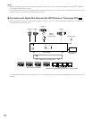
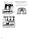
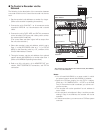
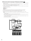
● To Control a Recorder via the
Network
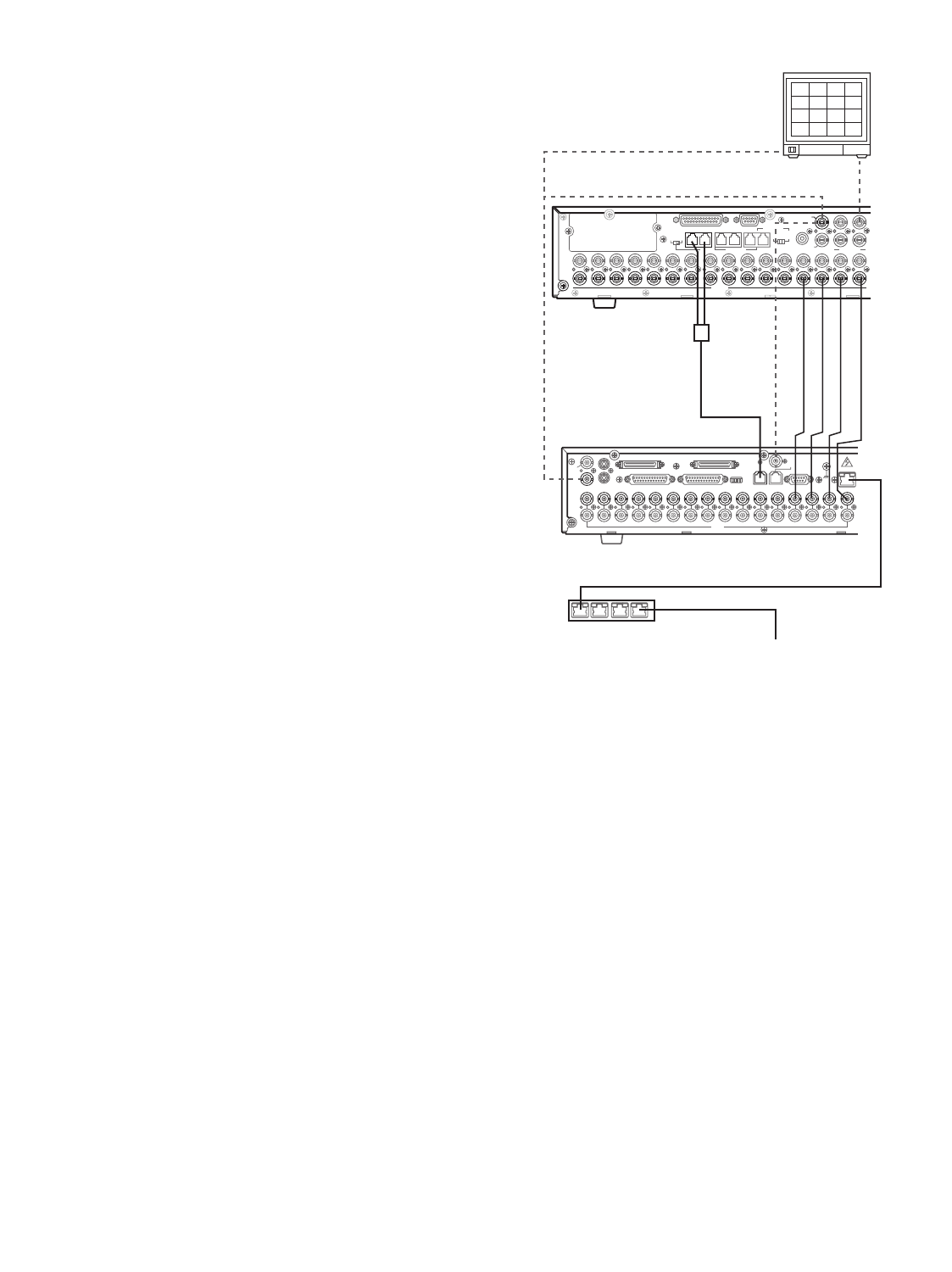
The following is the description of the connection between
a recorder and this unit to control the recorder via the net-
work.
1. Set the recorder's unit address to a number 5 or larger .
(Refer to the recorder's operating instructions.)
2. Connect the unit’s CAM OUT 1 to 16 connectors to the
recorder’s VIDEO IN 1 to 16 connectors with a coaxial
cable.
3. Connect the unit’s DATA HDR and DATA4 connectors
to the recorder’s DATA port with a daisy chain connec-
tion cable kit (WV-CA48/10K).
(The control data and alarm signal will be output from
the unit to the recorder.)
4. Select the recorder’s new unit address, which is set in
Step 1, in 600 RECORDER (refer to p. 71 ) of SETUP
MENU or the Recorder (refer to p. 97 ) window of WJ-
SX150A Administrator Console.
5. Through a browser, set the unit address of an optional
network board (WJ-HDB502) to a number other than 1.
(Refer to WJ-HDB502 Operating Instructions.)
6. Refer to p. 38, p. 40 and p. 41 for MONITOR OUT con-
nection, MULTI SCREEN OUT connection, and EXT IN
connection.
Notes:
• You will need WJ-HD500A or a newer model, in which
an optional network board (WJ-HDB502) is installed.
• Select the PS·Data protocol for the DATA 4 setting.
(Refer to p. 74 CAMERA/DATA1 - 4 PORT or p. 96 Data
Port.) If the terminal mode is selected, you cannot con-
trol the recorder.
• The recorder will not be operable if its unit address is
set to 1/2/3/4.
• If the recorder's unit address in Step 1 and the recorder
setting in Step 4 are different, the recorder will not be
operable.
• In these connections, you cannot use a PS·Data system
controller.
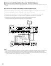
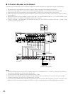
Matrix Switcher
Monitor
Recorder*
16
16
15
15
14
14
13
13
12
12
11
11
10
10
9
9
8
8
7
7
6
6
5
5
4
4
3 2
2
3
1
1
SIGNAL GND
10/100BASE-T
SPOT
OUT
IN EXT STORAGE COPY
CONTROL ALARM
VIDEO
MODE
DATA
REMOTE(WV-CU50)
GEN-LOCK OUT
SERIAL
IN
OUT
OUT
MULTI SCREEN OUT
AUDIO
* WJ-HD500A or Newer Models with Network Board (WJ-HDB502)
** LAN : Local Area Network
CAMERA
1
1
2
2
3
3
2
DATA 3 DATA 2
SERIALALARM
TERM
OFF ON
4
2
1
4
3
EXT OUT
(REC OUT)
CAMERA
SW IN
RS485(CAMERA)
LINE
SELECT
MONITOR OUT
EXT IN
(PLAY IN)
OUT
IN
4
4
5
5
6
6
7
7
8
8
9
9
10
10
11
11
12
12
13
13
14
14
15
15
16
16
RS485(CAMERA)PS•DATA
DATA 4DATA HDR DATA 1
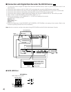
EXT IN
MULTI SCREEN
OUT
DATA HDR
DATA
DATA4
(PS·Data)
MONITOR
OUT
Daisy Chain Connection Kit
(WV-CA48/10K)
HUB/Router
LAN Cable
10/100 BASE-T
LAN**