


53
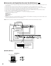
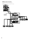
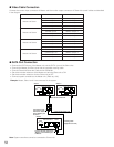
● Video Cable Connection
Connect the camera input connectors of Master and the monitor output connectors of Slave with coaxial cables as described
in the diagram.
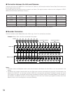
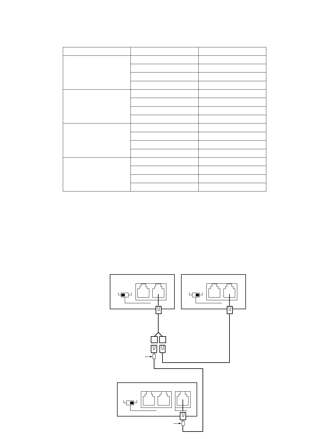
● DATA Port Connection
• Connect the DATA 3 port of the Master unit and the DATA 4 port of the Slave units.
• Connect the Master and Slave units with the supplied crossing cable.
• Connect Slave and Slave with Cable Kit WV-CA48/10K.
• Set the termination selectors of the Master and terminal Slave unit to ON.
• Set the termination selectors of other Slave units to OFF.
• Connect system controllers to the Master unit. (Refer to p. 39.)
Note: System controllers cannot be connected to Slave units.
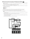
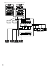
Connection Master Slave
Master and Slave 1
Master and Slave 2
Camera Input 1 Monitor Output 1
Camera Input 2 Monitor Output 2
Camera Input 3 Monitor Output 3
Camera Input 4 Monitor Output 4
Camera Input 5 Monitor Output 1
Camera Input 6 Monitor Output 2
Camera Input 7 Monitor Output 3
Camera Input 8 Monitor Output 4
Monitor Output 1
Monitor Output 2
Monitor Output 3
Monitor Output 4
Monitor Output 1
Monitor Output 2
Monitor Output 3
Monitor Output 4
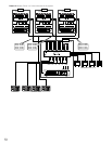
Master and Slave 3
Camera Input 9
Camera Input 10
Camera Input 11
Camera Input 12
Master and Slave 4
Camera Input 13
Camera Input 14
Camera Input 15
Camera Input 16
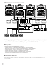
TERM
OFF ON
PS•DATA
DATA 4DATA HDR
TERM
OFF ON
PS•DATA
DATA 4DATA HDR
DATA 3
TERM
OFF ON
PS•DATA
DATA 4DATA HDR
Slave 1 Slave 2
Cable Kit WV-CA48/10K
Cable Kit WV-CA48/10K
Connect the side
marked as “Slave”
to the DATA 4 port
of Slave 1.
Crossing cable
(supplied to the unit)
Connect the side marked as
“Master” to the DATA 3 port
of Master.
Master
Example: Master, Slave 1 and 2 are connected in the system.