


47
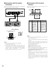
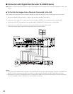
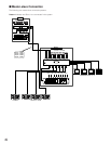
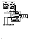
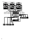
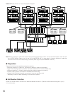
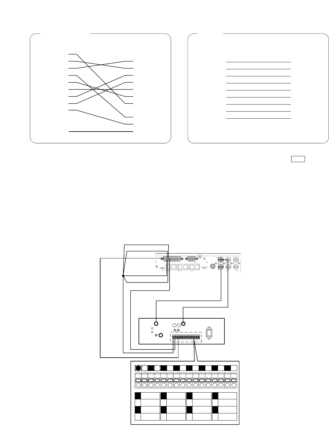
■ Connection with the Time-lapse VCR (Non-Panasonic Models)
1. To record the camera images through a time-lapse VCR, install an optional Multiplexer board in the matrix switcher.
2. Select OFF for 600 RECORDER in SETUP MENU. (Refer to p. 71.)
3. Connect the matrix switcher’s EXT OUT (REC OUT) to the time-lapse VCR’s video input connector with the coaxial cable.
4. Connect the matrix switcher’s EXT IN (PLAY IN) to the time-lapse VCR’s video output connector with the coaxial cable.
Notes:
• To use the alarm recording function, connect the matrix switcher’s all alarm output terminals (Alarm Output 1 to 4) to the
time-lapse VCR’s ALARM IN.
• Be sure to set the VCR to automatically recover from alarm reset.
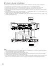
MUX
VIDEO IN
CAMERA
SW OUT
GND
S-VIDEO
AUDIO
VIDEO OUT
1
2
1 2 3 4 5 6 7 8 9 10 11 12 13 14 15 16
1
2
3
4
ALARM
IN
COM
ALARM
RESET IN
ALARM
RECOVER OUT
5
6
7
8
ALARM
OUT
1 SHOT IN
TAPE END
OUT
9
10
11
12
WARNING
OUT
HUMID OUT
REC REVIEW
OUT
13
14
15
16
SERIES
REC IN
TIME
ADJUST IN
TIME
ADJUST OUT
COM REC OUT
SERIES
REC OUT
Time-lapse VCR
Matrix Switcher
2
DATA 3 DATA 2
SERIALALARM
TERM
OFF ON
4
2
1
4
3
CAMERA
SW IN
RS485(CAMERA)
LINE
SELECT
MONITOR OUT
EXT IN
(PLAY IN)
EXT OUT
(
REC OUT
)
RS485(CAMERA)
DATA 4DATA HDR
PS•DATA
DATA 1
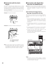
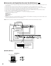
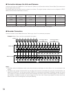
Pin #23(Alarm out 2)
Pin #9(GND)
Pin #24(Alarm out 4)
Pin #10(Alarm out 1)
Pin #11(Alarm out 3)
Pin #13
(Recover Input)
4
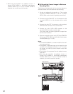
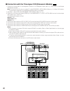
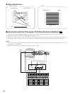
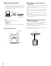
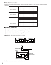
● Cable Specifications
1
2
3
4
5
6
7
8
9
Frame
1
2
3
4
5
6
7
8
20
22
Frame
Shield
Time-lapse VCRMatrix Switcher
AG6730, AG6740
1
2
3
4
5
6
7
8
9
1
2
3
4
5
6
7
8
9
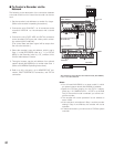
Straight Cable
RT850Matrix Switcher
RT850