


40
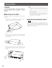
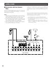
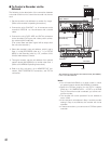
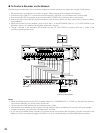
■ Connection with Digital Disk
Recorder WJ-HD500 Series
Note: Refer to a service manual procurable in your area, for
details on the connection with a recorder (after the net-
work board installation) to operate via LAN or the
Internet.
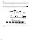
● To Confirm the Images from a
Recorder Connected to the Unit
The following is the description of the connection between a
recorder and this unit to confirm the images from the
recorder.
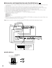
1. Set the unit address of the recorder to 1. Then, confirm
that the recorder’s CAMERA GENLOCK is set to OFF in
its SETUP MENU. (Refer to the recorder's operating
instructions.)
2. Connect the unit’s CAM OUT 1 to 16 connectors to the
recorder’s VIDEO IN 1 to 16 connectors with a coaxial
cable.
3. Connect the unit’s EXT IN connector to the recorder’s
MULTI SCREEN OUT connector with a coaxial cable.
4. Connect the unit’s DATA HDR connector to the
recorder’s DATA port with a modular cable.
(The control data and alarm signal will be output from
the unit to the recorder.)
Notes:
• You cannot record the camera images in maximum
recording rate through this connection. Refer to the next
connection example in this page.
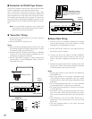
Matrix Switcher
Monitor
Recorder
16
16
15
15
14
14
13
13
12
12
11
11
10
10
9
9
8
8
7
7
6
6
5
5
4
4
3 2
2
3
1
1
SIGNAL GND
10/100BASE-T
SPOT
OUT
IN EXT STORAGE COPY
CONTROL ALARM
VIDEO
MODE
DATA
REMOTE(WV-CU50)
GEN-LOCK OUT
SERIAL
IN
OUT
OUT
MULTI SCREEN OUT
AUDIO
CAMERA
1
1
2
2
3
3
2
DATA 3 DATA 2
SERIALALARM
TERM
OFF ON
4
2
1
4
3
EXT OUT
(REC OUT)
CAMERA
SW IN
RS485(CAMERA)
LINE
SELECT
MONITOR OUT
EXT IN
(PLAY IN)
OUT
IN
4
4
5
5
6
6
7
7
8
8
9
9
10
10
11
11
12
12
13
13
14
14
15
15
16
16
RS485(CAMERA)PS•DATA
DATA 4DATA HDR DATA 1
EXT IN
MULTI SCREEN
OUT
DATA HDR
MONITOR
OUT
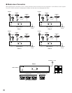
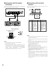
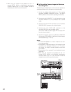
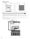
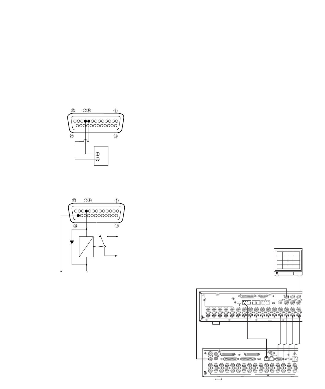
■ Connection with the Alarm
Output
Pins #10, 11, 23 and 24 (open collector) turns to 0 V while
the alarm is activated. These terminals can drive external
warning devices such as a buzzer or lamp of up to 100 mA,
16 V DC. If the rating exceeds 100 mA, 16 V DC use a relay
as shown in Example 2.
Alarm signals are output from the terminals until the reset.
Example 1: Direct drive connection
Example 2: Connection of devices exceeding drive
Note: An alarm signal is output from the Master unit and a
unit activated by the alarm. Be careful of connections
as the Master unit outputs alarm signals to directly-con-
nected devices any time when an alarm is activated.
NO
C
NC
To Buzzer
Relay
+12V
GND
NC: Normally Closed Contact
NO: Normally Open Contact
C: Common
Buzzer