


88
ON: The alarm-associated sequence/spot image is dis-
played on a monitor, and alarm recording will start
(if a recorder is connected to the unit).
REC ONLY: Only an alarm recording will start and
monitors will keep displaying the current sequence/
spot images.
Note: You cannot recover alarm-related operations
from system controllers when REC ONLY is
selected.
OFF: An alarm input is accepted neither via the CAM-
ERA IN connectors nor the RS-485 ports.
The factory default setting is OFF.
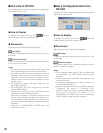
Alarm Port
This stands for that an alarm input is accepted via the
ALARM port (25-pin D-sub connector) at the rear panel.
ON: The alarm-associated sequence/spot image is dis-
played on a monitor, and alarm recording will start
(if a recorder is connected to the unit).
REC ONLY: Only an alarm recording will start and
monitors will keep displaying the current sequence/
spot images.
Note: You cannot recover alarm-related operations
from system controllers when REC ONLY is
selected.
OFF: An alarm input is not accepted via the ALARM
port.
The factory default setting is ON.
Serial Port
This stands for that an alarm input is accepted via the
SERIAL port.
ON: The alarm-associated sequence/spot image is dis-
played on a monitor, and alarm recording will start
(if a recorder is connected to the unit).
REC ONLY: Only an alarm recording will start and
monitors will keep displaying the current sequence/
spot images.
Note: You cannot recover alarm-related operations
from system controllers when REC ONLY is
selected.
OFF: An alarm input is not accepted via the SERIAL
port.
The factory default setting is ON.
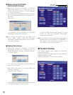
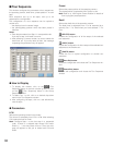
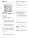
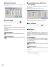
■ Alarm Mode
This window configures the operation parameters when an
alarm signal is input: an alarm mode, auto reset time and
alarm input.
● How to Display
To display this window, click on the (Alarm Mode) but-
ton in the main window (p. 80).
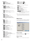
● Parameters
• Alarm Mode
Checking on the box of the desired alarm mode.
OFF: The system operation does not change into any
other mode.
Sequence Mode: Camera images are displayed on the
monitor in either the spot mode or tour sequence.
When more than one alarm are input, the image
associated to each alarm is displayed in the
sequence mode.
Note: Click on the Dwell drop-down menu to select
the dwell time.
Hold Mode: Camera images are displayed on the mon-
itor in either the spot mode or tour sequence. Even
more than one alarm are input, the image associat-
ed to the initial alarm is continuously displayed.
Notes:
• The alarm mode is activated when alarm input signals
are assigned to the same monitor through 420 ALARM
EVENT or the Alarm Event (refer to pp. 67 and 68/ p.
89) window.
• While alarm is activated, you cannot operate the func-
tions related to the Multiplexer board.
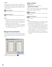
• Alarm Input Group
Select the alarm input to be accepted. Multiple Selection is
available.
Camera
This stands for that an alarm input is accepted via the
CAMERA IN connectors or the RS-485 ports.