


Appendixes
- App. 57 -
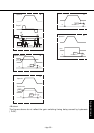
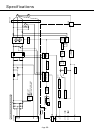
• Control Block Diagram
Pulse command
PULS
SIGN
Feedback pulse(OA • OB)
Feedback pulse(OZ • CZ)
Encoder signal
A/B phase or Rx
Encoder signal (Z phase)
++
+
+
-
-
Input mode
selection
[Pr42]
Smoothing
filter
Pr4C
Position 2
[Pr18]
Position 1
[Pr10]
Position
error counter
Position
error amplifier
2nd [Pr18]
1st [Pr13]
Speed detection filter
Width [Pr1E]
Frequency [Pr1D]
Selected by Pr02
Notch filter
Pr5E
Torque limit
Torque command
2nd [Pr1C]
1st [Pr14]
Torque command filter
Control mode switching
Velocity feed
forward
Pr15
Feed forward
filter
Pr16
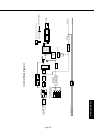
Denominator
Pr46
Pr4B
Pr53
Pr54
Pr55
Pr56
Pr44
Multiplier
Pr4A
Numerator X
2
Scaling
Internal 1st speed
Internal 2nd speed
Internal 3rd speed
Internal 4th speed
Switching between internal and
external velocity setting
Acceleration, deceleration
and S-curve accel./decel. time
Output pulse per
single turn[Pr44]
Multiplier of 4
speed
detection
P
T
P/S
S
P
: Velocity control mode
: Position control mode
Block for servo gains and filter time constants
S
Pr02
Acceleration time [Pr58]
Deceleration time [Pr59]
S-curve accel./decel. time [Pr5A]
Velocity, 2nd [Pr19]
Integration, 2nd [Pr1A]
Velocity, 1st [Pr11]
Integration, 1st [Pr12]
Inertia ratio [Pr20]
Velocity error amplifier
PANATERM
®
Monitoring the sum of
command pulses
PANATERM
®
Monitoring feedback pulses
PANATERM
®
Wave form graphics
(actual velocity)
Wave form
graphics speed
command
PANATERM
®
Wave form graphics
Velocity command
PANATERM
®
Only position control mode