- 47 -
No.
0
5
Input signal
Servo-ON
Speed zero clamp
Monitor display
+ A
----
Stop with +A
Input Signal Status
PrNo.
Pr02
Pr04
Pr06
Pr53
~
Pr56
Pr58
Pr59
Pr5A
Parameter description
Control mode set-up
Overtravel input inhibit
ZEROSPD input selection
Acceleration time set-up
Deceleration time set-up
S-shaped accel/decel time set-up
Value
1
1
1
Set as re-
quired
Default
0
1
1
0
0
0
0
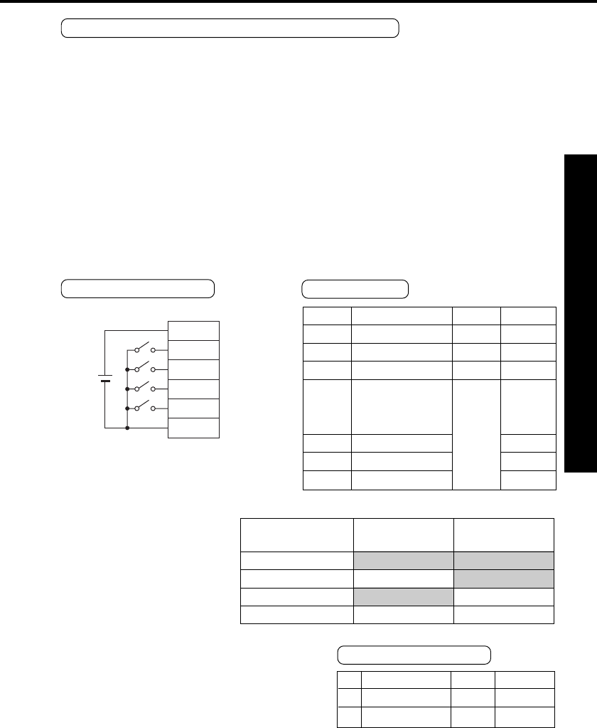
Test Run at Internal Velocity Control Mode
1) Select the internal velocity control mode (Pr02: 1) for the control mode.
2) Run with zero speed clamp input (ZEROSPD) (5 pin) switch close, and rotate the motor with the
combination of the internal command speed selection INTSPD 1 (6 pin) and INTSPD 2 (4 pin).
3) Check the motor speed on the PANATERM
“
monitor.
ÅE
Speed and direction
4) Make sure that the motor stops by making zero speed clamp input (ZEROSPD) open.
5) To change the speed or direction, adjust the following parameters again.
Pr53 - Pr56: Velocity set-up for 1st speed through 4th speed See "Details of Parameters"
in Appendix 31.
Preparations and Adjustments
Parameters
Wiring Diagram
Velocity
set-up
1st speed
through
4th speed
COM+
SRV-ON
ZEROSPD
INTSPD2
INTSPD1
COM
-
1
2
4
6
5
DC
12V~24V
ZEROSPD
switch
Close: Run
Open: Stop
Internal speed
1st speed (Pr53)
2nd speed (Pr54)
3rd speed (Pr55)
4th speed (Pr56)
DIV/INTSPD1
(6 pin)
OPEN
CLOSE
OPEN
CLOSE
CL/INTSPD2
(4 pin)
OPEN
OPEN
CLOSE
CLOSE


