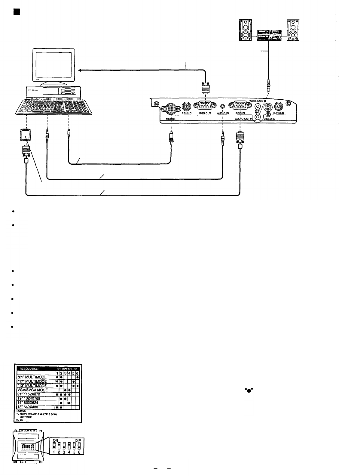
Example of connection to a computer
Audio system
Diagram numbers correspond with numbers (see page 30).
Computer
Computer
Monitor Cable
4 (Audio Cable)
(not included)
Connector jacks on
left side of Projector
3 (PS/2 Mouse Cable) or
4 (MAC Mouse Cable)
PC Audio Cable (not included)
2 (VGA MAC Adapter)
1 (VGA Cable)
Note:
The RGB input accepts signals from VGA, SVGA, XGA (Compression), and MAC compatible computers without
the need for any additional hardware.
Plug the VGA signal cable (supplied) correctly into the RGB IN terminal on the LCD Projector and the RGB signal
Output terminal on your computer. Secure the plugs by tightening the thumb screws.
When connecting the LCD Projector to a Macintosh Series computer, first connect the VGA/MAC adaptor
(supplied) to the RGB-signal input terminal on your computer. Then, firmly plug the VGA signal cable into both
the RGB IN terminal on the LCD Projector and the VGA/MAC adaptor on the computer. Secure the plugs by
tightening the thumb screws. Be sure to set the DIP switch on the VGA-MAC adapter to your display type. (See
the bottom of this page.)
To view images simultaneously on the monitor and projection screen, connect your computer monitor to the LCD
Projectors RGB OUT terminal.
When the LCD Projector is connected to personal computer, you can use the remote control in place of the
computers mouse by attaching the Mouse cable.
If you wish to use the wireless mouse function, turn on the main power to the Projector before turning on the
personal computer.
When connecting the LCD Projector to a compatible computer other than a VGA, SVGA, XGA (Compression), or
Macintosh series, a separate cable is needed.
If you wish to use the plug & play function, turn on the MAIN power switch on the LCD Projector before turning on
the computer.
[VGA-MAC adapter]
[Setting the DIP Switches]
Find the resolution of your display type on the table shown left (also on the
adaptor). Then, set each DIP switch that is indicated by a mark to ON.
Example: If your display type is 16”, set DIP switches 2 and 4 on the VGA-MAC
adaptor to ON. By doing so, the signal will travel through switches 2 and 4, and Pin
No. 4 to 10 as shown in the signal chart above.
29


