


COMSPHERE 392xPlus Modems
2-2 November 1996 3920-A2-GN31-30
For
the carrier-mounted models
• Installation instructions
•
Model 3921
Plus modem
• One (singleport) or two (multiport) connector plates with two DB-25-S edge card connectors
on each plate
If any hardware components are damaged, notify your service representative. Return equipment
using the procedures described in the
Government Requir
ements and Equipment Return section of
Chapter 1.
Customer-Supplied Equipment
The following customer
-supplied equipment is required to complete a data communications system
using the Model 3920
Plus modem:
• One (singleport) or four (multiport) DTEs with available EIA-232-D serial port(s).
• Standard EIA-232-D cables with one (singleport) or four (multiport) DB-25-P connectors at
one end to attach to the modem.
• One or more of the following modular leased or dial network interfaces:
— JM8 for leased-line configurations.
— RJ11C for dial permissive configurations.
— One 8-position, 8-wire modular cord (for leased backup purposes).
The following customer-supplied equipment is required for the installation of a Model 3921Plus
modem:
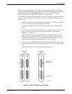
• A COMSPHERE 3000 Series Carrier.
• A 50-pin mass termination cable.
• One or more of the following modular or 50-pin leased or dial network interfaces:
— RJ11C for single-line dial permissive configurations.
— RJ21X for multiple-line dial permissive configurations.
— 66 punchdown block.
• One Network Interface Module (NIM) for modems installed in Slots 1–8 and one NIM for
modems installed in Slots 9–16 (required for dial-line configurations).
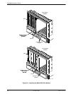
For installation of the COMSPHERE 3000 Series Carrier into a cabinet, refer to the COMSPHERE
3000 Series Carrier
, Installation Manual.