


Modem Installation
2-53920-A2-GN31-30 November 1996
Power Supply Connection
Use the following steps to connect the modem to an ac power outlet:
1.
Make sure the modem is powered OFF
.
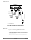
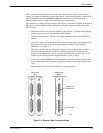
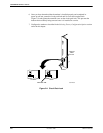
2. Insert the power supply’s 8-pin DIN connector into the modem’
s back panel dc power
receptacle, labeled PWR
(Figure 2-1).
3. Connect the power cord to the power supply.
4. Connect the power cord to a grounded ac power outlet.
Leased-Line Connection
Use the following steps to connect the leased-line network interface:
1. Insert the 8-position, 8-conductor modular plug into the jack labeled LEASED
(Figure 2-1).
2. Insert the other end of the modular cord into the leased-line network interface.
3. If the Model 3920Plus
has a backup line, follow the steps listed in the
Dial Backup
Connection
section.
Dial Connection
The telephone company provides the line termination jacks for the permissive service you request.
Advance coordination with the telephone company is suggested when connecting the modem to
telephone dial lines (PSTN).
In the Permissive mode, the modem’s transmit output level is fixed at –9 dBm. The telephone
company assumes that the line loss is 3 dB and no compensation is provided for additional losses.
A Permissive mode telephone line is usually terminated with a USOC RJ1
1C jack.
Leased Backup Connection
Use the following steps to connect the modem to the 2-wire leased backup network interface:
1. Insert the 8-position, 8-conductor modular plug into the jack labeled DIAL (Figure 2-1).
2. Insert the other end of the modular cord into the leased-line network interface.
Dial Backup Connection
Use the following steps to connect the modem to the dial network interface:
1. Insert the 6-position, 4-conductor modular plug into the jack labeled DIAL (Figure 2-1).
2. Insert the other end of the modular cord into the dial network interface.