


DCP Operation
3-33920-A2-GN31-30 November 1996
Model 3920
Plus
Diagnostic Control Panel
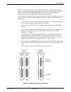
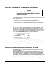
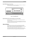
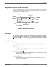
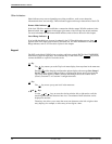
The diagnostic control panel (DCP) of the Model 3920Plus modem (Figure 3-1) contains status
indicators, pushbutton-type keys, an LCD, and speaker grill.
PWR ALRM
CTS TXD LSD RXD TEST
RATE
105
106
103
109
108 142
COMSPHERE 3920
Plus
496-14412-0
2
F1 F2
F3
SQRTS
DTR
104
DIAG
DIAL
Figure 3-1. Model 3920
Plus
DCP
Model 3921
Plus
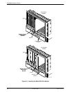
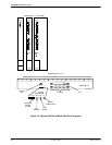
Faceplate and Shared Diagnostic Control Panel (SDCP)
The shared diagnostic control panel (SDCP), Figure 3-2, is used to manage carrier-mounted
Model 3921
Plus
modems.
The faceplate of the Model 3921Plus contains LED status indicators that monitor the operation of
the modem. After the SDCP is connected to the modem, the Front Panel indicator of the selected
modem lights to show that the modem is connected.
Status Indicators
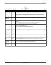
The 392xPlus modem status indicators continuously provide information on the modem’s
operating condition. All of the status indicators on the Model 3920Plus
appear on the DCP
(Figure 3-1), whereas the status indicators for the carrier-mounted Model 3921Plus are located on
the Model 3921
Plus modem’s faceplate and the SDCP faceplate (Figure 3-2).
The standalone Model 3920
Plus modem’s DCP has 13 light-emitting diodes (LEDs), and the
carrier-mounted Model 3921Plus has 20 LEDs. These LEDs are listed and described in Table 3-1.
LEDs specific to one model type have the appropriate model number shown in the table.