


COMSPHERE 392xPlus Modems
2-4 November 1996 3920-A2-GN31-30
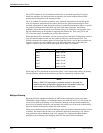
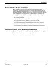
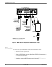
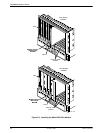
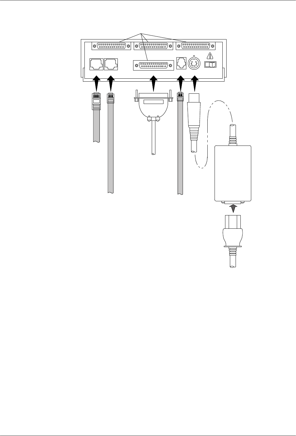
8-POSITION,
8-CONDUCTOR
PLUG FOR
LEASED-LINE
NETWORK
OPERATION
6-POSITION,
4-CONDUCTOR
PLUG FOR
PERMISSIVE
DIAL
NETWORK
OPERATION
DB-25-P
CONNECTOR
FOR DATA
TERMINAL
EQUIPMENT
OPERATION
SUB-MINIATURE,
4-POSITION,
4-CONDUCTOR
PLUG FOR
NETWORK
MANAGEMENT
SYSTEM
OPERATION
POWER
SUPPLY
DTE
2
DTE 3 DTE 4
DTE 1LEASED DIAL NMS PWR ON OFF
NOTE: THE DIAL JACK IS ALSO USED
FOR 2-WIRE LEASED BACKUP.
POWER
CORD
DB-25-S CONNECTORS
Figure 2-1. Model 3920
Plus
Multiport Back Panel and Power Supply
DTE Connection
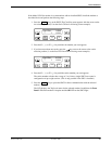
Use the following steps to connect an EIA-232-D cable from the modem to a DTE:
1.
Make sure the modem is powered OFF
.
2. Connect the DB-25-P (plug) connector on the cable to a DB-25-S (socket) connector
(Figure 2-1) on the modem’s back panel, labeled DTE 1—DTE 4. Use a small screwdriver
to secure the cable to the modem.
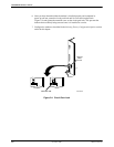
3. For each port, connect the DB-25-P connector on the cable to the DB-25-S connector on
the DTE. Use a small screwdriver to secure the cable to the DTE(s).