4. Configuration Options
4-38
September 2002 9128-A2-GB20-80
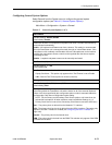
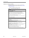
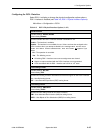
Configuring a User Data Port (CSU/DSUs)
Select Physical from the Data Ports menu to display or change the physical
characteristics of the data port connected to the DTE (see Table 4-7, Data Port
Physical Interface Options).
Main Menu
→
Configuration
→
Data Ports
→
Physical
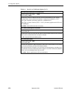
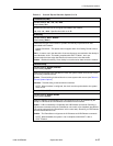
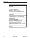
Table 4-7. Data Port Physical Interface Options (1 of 5)
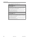
Port Status
Possible Settings: Enable, Disable
Default Setting: Enable
Determines whether the data port is being used and can be configured.
Enable – The port is active, and can be used to transmit and receive data.
Disable – The port is not active. When the port is disabled, the following will occur:
No alarms or traps configured for the port will be generated.
LED for the port will be held in an Off state.
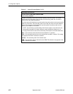
No – The operation is cancelled. (Pressing either the Esc or Ctrl-a key also acts as a
No.)
Yes – Port status is disabled.
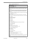
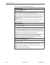
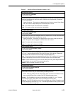
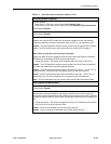
Port Use
Possible Settings: Frame Relay, Synchronous Data
Default Setting:
Frame Relay when the port supports frame relay.
Synchronous Data when the port only supports synchronous data.
Determines how the data port will be used.
Display Conditions
– This option only appears for user data on Port-2.
Frame Relay – The port is configured for frame relay traffic. Frame relay links, DLCis, and
PVC connections can be configured on this port.
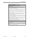
Synchronous Data – The port is configured for standard TDM data, and can be
cross-connected to a time slot on a T1 interface.
No alarms or traps configured for the port will be generated.
The LED for the port will be held in an Off state.
Existing cross-connect assignments associated with the port are cleared.


