C1522M-C (2/05) 29
LOCAL AUXILIARIES
The CM6800-32X6 provides two local auxiliary (AUX) outputs on the rear panel for controlling VCRs, printers, and other devices. These
outputs can be activated directly from a keyboard by using the F1 and F2 function keys, or they can be activated by an alarm (determined
by programming). Both relay contacts and TTL outputs are used.
In addition, you can connect up to two REL2064 Relay Interface Units to the CM6800. Note that since operation of the two internal
auxiliary relays on the CM6800-32X6 will also operate the first two relays on the external unit, the maximum capacity of the system may
be limited to 128 auxiliaries (depending on how you number the external relays). Refer to the
Connecting a Single REL2064 Relay Interface
Unit
section for connection instructions.
Connecting Relay Contacts – AUX 1
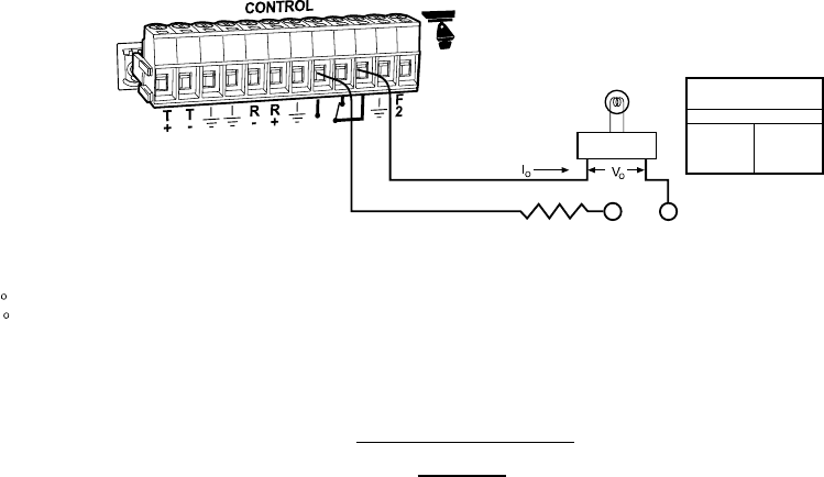
AUX 1 is a dry contact relay output. Terminal connections are provided for both normally open (N.O.) and normally closed (N.C.) contacts.
Refer to Figure 23 for wiring details. Note that this figure shows the wiring for a normally open contact. For a normally closed contact,
move the wire from the N.O. terminal to the the N.C. terminal.
Do not exceed the voltage and current ratings for the relay contacts.
You will need to provide an external power source to operate your device. In most cases you will also need an external current limiting
resistor. The formula for calculating the resistor value is given in Figure 23.
12-PIN PLUG-IN
CONNECTOR
FORMULAS FOR R VALUES
R (OHMS) = VPS - V
O
I
O
P (WATTS) = (I ) X R
2
O
= OPERATING CURRENT OF THE EXTERNAL DEVICE (MUST NOT EXCEED AUX 1 CURRENT RATING.)
= RATED OPERATING VOLTAGE OF THE EXTERNAL DEVICE.
= CURRENT LIMITING RESISTOR.
= VOLTAGE OF THE EXTERNAL POWER SOURCE (MUST NOT EXCEED VOLTAGE RATING FOR THE
ASSOCIATED CURRENT). VPS CAN BE AC OR DC.
= NEGATIVE, COMMON OR GROUND TERMINAL OF EXTERNAL POWER SOURCE (AC OR DC).
I
V
R
+VPS
-VPS
AUX 1 RELAY
CONTACT RATINGS
CURRENT
@
VOLTAGE
1A
0.3A
0.5A
30 VDC
110 VDC
125 VDC
EXTERNAL
DEVICE
-VPS
+VPS
R
Figure 23. Wiring the AUX 1 (Relay) Output
