C1522M-C (2/05) 61
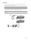
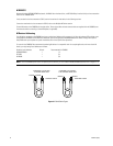
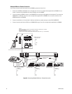
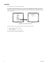
CONTROL GENEX MULTIPLEXER AND GENEX MULTIPLEXER DISPLAYS
Multiplexer control is not available with the KBD100.
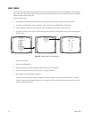
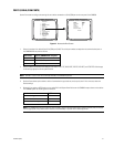
KBD200A/300A KEYBOARDS
1. Enter the number of the multiplexer input.
2. Press the CAM key.
3. Press the SHIFT key. When the SHIFT LED is lit, the keyboard can
be used to operate the following Genex multiplexer function keys:
F1: Digital zoom
F2: PIP display
F3: Quad display
AUX ON/F4: 9-screen display
AUX OFF/F5: 16-screen display
To select a camera through the multiplexer:
a. Enter the desired camera number (1-16, based on the camera
assignments set through the multiplexer).
b. Press the CAM key.
4. Press the SHIFT key to return to normal keyboard operation.
When the SHIFT LED is off, you can control the currently selected
PTZ camera through the multiplexer.
To return to camera selection controlled by the CM6800E:
a. Select the desired camera number.
b. Press the CAM key.
c. Move the joystick as necessary.
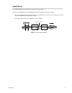
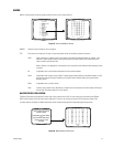
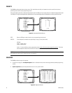
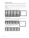
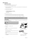
KBD960/KBR960 KEYBOARDS
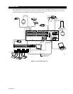
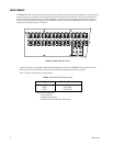
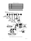
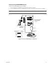
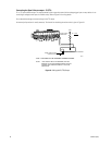
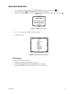
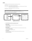
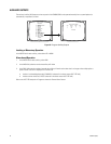
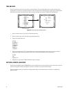
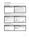
1. Enter a MUX input number and press
. Each MUX
input is associated with a camera input. Figure 43
shows MUX 1 being controlled.
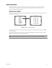
2. Select
MUX
. MUX Menu 1 appears.
MUX
should be
highlighted, which means you have MUX control.
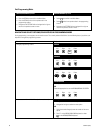
3. Cycle through the 16 picture inserts (if yo have a
16-channel multiplexer) by entering the camera number
and selecting
.
4. Select
again to zoom into the MUX camera. You
can move the joystick to view a specific area.
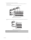
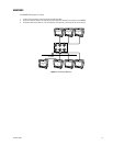
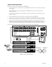
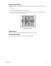
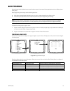
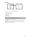
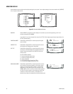
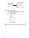
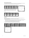
5. Select
to bring up MUX Menu 2. The icons for a
picture-in-picture display, 4-camera display, 9-camera
display, and 16-camera display appear.
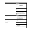
6. Select
to view four of the available 16 cameras on
one monitor. You can cycle through all 16 cameras, four
at a time, by repeatedly selecting .
7. Select
to view nine of the available 16 cameras on
one monitor. Select again to see the remaining seven
cameras.
8. Select
to view all 16 available cameras on one
monitor.
Note that
does not work on a 9-channel
mulitplexer.
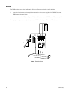
OPERATE SCANNING FUNCTIONS
Operation of the scanning functions depends on the kind of receiver or pan/tilt mechanism you have. Refer to the appropriate keyboard
manual for detailed instructions on operating scanning functions.
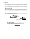
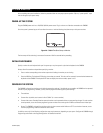
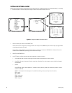
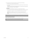
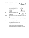
DETECT VIDEO LOSS
The CM6800 detects video loss from any system camera. If video is lost from a camera, the CM6800 blue screen appears on any monitor
viewing that camera. When video is restored to that camera, the camera view appears on the monitor(s) again. If the system is pro-
grammed for a video loss alarm, the alarm icon appears.
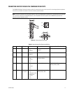
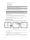
DEFINE ZONES
A zone is a user-defined, physical location to which (1) a label is attached and (2) a camera is associated. When the associated camera is
panned through or remains within this defined zone the zone label appears on the monitor.
Refer to the appropriate keyboard manual for detailed instructions on defining zones.