


C1522M-C (2/05) 17
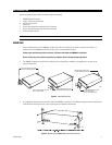
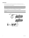
CONNECTING DEVICES THROUGH THE COMMUNICATION PORTS
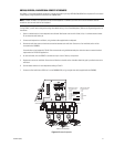
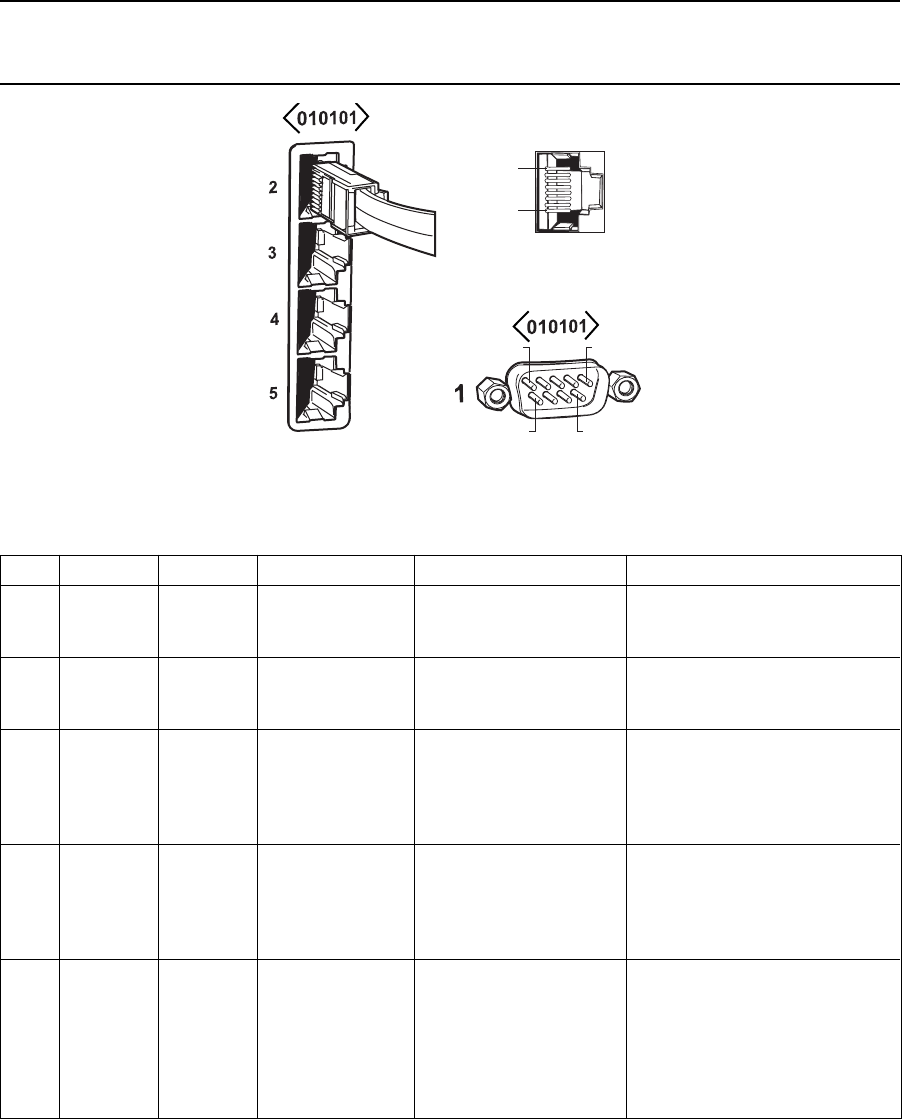
The CM6800-32X6 Matrix Switcher/Controller provides five communication ports on the rear panel for connecting peripheral components.
Instructions are provided in this section for the most commonly used connections.
NOTE: Connection instructions for other periperal devices, such as the CM9760-MDA or CM9760-CDU-T, are provided as Pelco Technical
Tips. Connection instructions for compatible products, such as PelcoNet transmission systems and the VMX300 are provided in the
appropriate product installation manual.
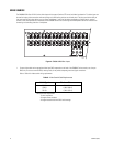
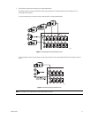
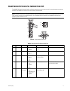
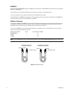
Figure 10. Communication Port Inputs
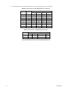
Table B. Communication Port Devices and Wiring
Port Input Type Wiring Pin-Outs Default Device Programmable to Other Device(s)
1 DB9 RS-232 2 Rx PC Setup – CM6800MGR ASCII device
3Tx program
5 Ground
2 RJ-45 RS-232 1 Rx ASCII device No
5 Ground
8Tx
3 RJ-45 RS-485 1 Rx+ M devices – ALM2064, No
2 Rx- REL2064, KBD960
5 Ground
7 Tx-
8 Tx+
4 RJ-45 RS-485 1 Rx+ Genex multiplexer CM9760-MDA, ASCII, keyboards
2 Rx- (KBD100, 200A, & 300A)
5 Ground
7 Tx-
8 Tx+
5 RJ-45 RS-485 1 Rx+ Keyboard (direct powered) – No
plus power 2 Rx- KBD100, 200, & 300
3 KBD power (12V)
4 KBD Ground
5 Ground
7 Tx-
8 Tx+
PIN 1
PIN 8
PIN 5PIN 1
PIN 6
PIN 9