


C1522M-C (2/05) 51
PORTS (SERIAL/COM PORTS)
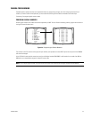
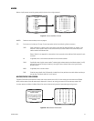
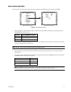
Use the Port screen to configure the settings for each device connected to a Serial/COM port on the rear panel of the CM6800.
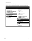
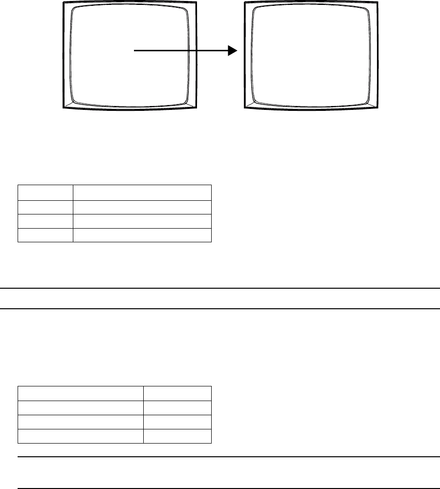
Figure 41. Access the Port Screen
1. Select the number of the desired Serial Port/COM port (01-06). The serial port numbers correspond to the communication ports on
the CM6800-32X6 rear panel as follows:
Serial Port Input on CM6800-32X6 rear panel
01 COM 1 DB9 input
02-05 COM 2-5 RJ-45 inputs
06 PTZ control input
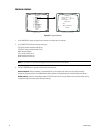
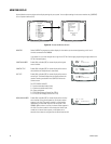
2. Select the device connected to the COM port; the values in the TYPE, BAUD RATE, PARITY, DATA BITS, and STOP BITS fields change
to the settings appropriate for the specific device.
NOTE: “KBD300” is used to refer to the KBD100, KBD200A, and KBD300A keyboards.
3. Optional: Some device options allow a choice of communication type, baud rate, and/or parity rate. If this is the case, select the
desired settings.
4. Optional: If you select an ASCII device you can select ON in the Report Alarm field to set the CM6800 to report alarms to that device.
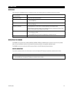
The CM6800 reports the following alarm information:
Action ASCII text
An alarm is triggered #Ea
An alarm is cleared #Ia
An alarm is acknowledged #Ka
NOTE: The CM6800-32X6 reports the physcial alarm number. If you use the eight internal alarm inputs on the rear panel, do not use
the first eight inputs on any external alarm interface units (ALM2064), or you will have a numbering conflict.
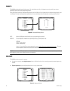
PELCO SWITCHER
MODEL CM6800
MAIN MENU
1 CAMERA
2 LOGICAL CAMERA
3 MONITOR
4 ACCESS
5 TIME & DATE
6 PORT
7 PRIORITY
8 SEQUENCE
9 MACRO
10 ALARM CONTACTS
11 EVENT TIMER
12 SET AUXILIARY
13 SET PASSWORD
14 ABOUT CM6800
ENGLISH
RETURN
00654
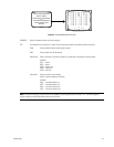
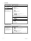
SET SERIAL PORT 05
DEVICE: KBD300
TYPE: RS485
BAUD RATE: 9600
PARITY: ODD
DATA BITS: 8
STOP BITS: 1
REPORT ALARMS: - - -
RETURN
00657