70 C1522M-C (2/05)
TROUBLESHOOTING
GAINING INITIAL CONTROL
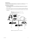
If you are having problems gaining control of your system for the first time:
• Confirm that all system equipment is plugged in and has power.
• Confirm that each keyboard and peripheral device in your system has a unique local address. Refer to the
Switch Settings
section in
the appropriate keyboard manual.
• Be sure data cables have not been mixed up.
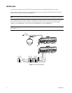
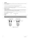
• Cycle the data cable to the keyboard:
1. Unplug the data cable from the rear of the keyboard.
2. Plug the data cable back into the rear of the keyboard.
3. WAIT AT LEAST FIVE SECONDS.
4. Select a monitor.
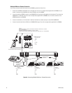
If you still cannot gain control of the system:
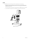
• Confirm the wiring is correct and the user-supplied cable between wall jacks is appropriate for the application.
• Confirm that when the keyboard data cable is cycled, the keyboard LED flashes momentarily (indicating power).
If you still cannot gain control of the system, call Pelco’s 24-hour technical support at 1-800-289-9100 or 1-559-292-1981.
NOTE: There are no userserviceable parts inside the CM6800. Only authorized service personnel may open the unit.
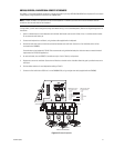
SOFTWARE RESET
Pelco strongly recommends uploading system settings to the CM6800-MGR before the software reset – this will allow you to restore
system settings after the software reset.
CAUTION: Resetting the software restores the system to default settings.
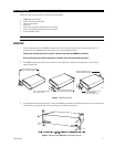
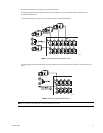
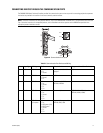
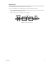
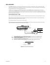
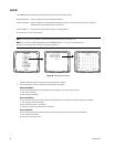
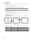
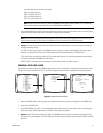
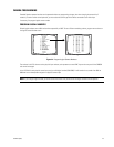
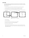
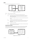
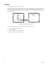
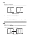
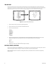
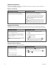
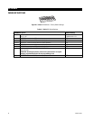
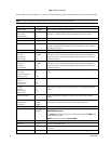
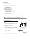
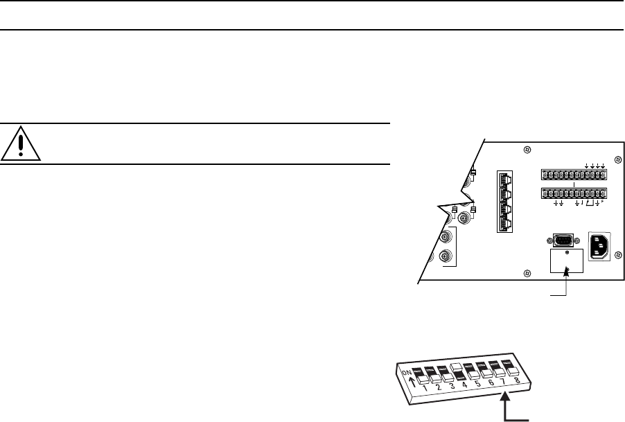
1. Remove the two screws and the DIP switch cover plate from the rear of the
matrix switcher.
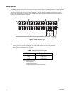
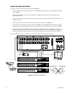
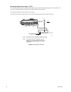
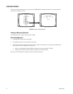
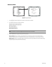
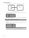
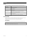
2. Move DIP switch 7 to the ON position (to “0”).
3. Cycle power.
The switcher will go through a software clear cycle and reset to factory
defaults.
4. Move DIP switch 7 to the OFF position.
Failure to move DIP switch 7 to the OFF position could result in loss of system
settings during a power outage.
5. Re-initialize keyboards by entering the monitor number and then pressing the
MON key.
6. Download your previous system settings (revise settings as necessary) from
the CM6800-MGR.
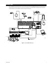
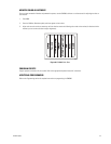
Figure 47. Dip Switch Cover Plate
Figure 48. CM6800 DIP Switch 7
COM 1
2
3
4
5
16
6
3231
3
VIDEO OUTPUTS
120/230V~
50/60 HZ
25 WATTS
COM
ALARM
12345678
CONTROL
T
+
T
-
R
+
R
-
2
PTZ
DIP SWITCH COVER PLATE
SWITCH 7:
ON = SOFTWARE RESET
OFF = NORMAL SYSTEM
OPERATION