C1528M-F (6/05) 49
Assign a Logical Alarm Number (Optional)
Each CM6800E alarm type (internal, external, and video loss) has been assigned a series of default logical alarm numbers, which start at
001 and continue sequentially. Depending on how you use the CM6800E system, the default logical alarm numbers could create a
numbering conflict, as described below.
Logical alarm numbers are used in the following ways:
• When an alarm is triggered, the logical alarm number, along with the alarm icon and the alarm letter (“I” for internal; “E” for
external; “V” for video) appears on monitors programmed through the Alarm Group screen to display the alarm. Using the default
logical alarm numbers is acceptable in this situation, because the alarm letter indicates what type of alarm is active.
• If you program the CM6800E to report alarms to an ASCII device (refer to the
Ports
section), then you must assign unique logical
alarm numbers to each alarm type. Otherwise numbering conflicts will occur; for example, an internal alarm numbered 001 would be
reported in the same way as an external alarm numbered 001.
• If you use the CM6800E as a satellite device in the CM9740/CM9760 system, and set the CM6800E to report alarms, then you must
assign each CM6800E alarm a logical alarm number that is unique within the CM9740/CM9760 system (i.e. when used as a satellite
device, the CM6800E shares the same pool of logical alarms numbers as the CM9740/CM9760 system).
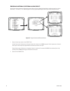
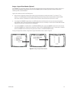
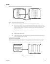
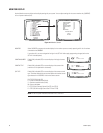
To assign new logical alarm numbers, navigate to the Logical Alarm Number menu as shown in Figure 37.
Figure 37. Assign a Logical Alarm Number
ALARM CONTACTS
1 INTERNAL CONTACT
2 EXTERNAL CONTACT
3 VIDEO LOSS
4 ALARM GROUP
5 LOGICAL ALARM NUMBER
RETURN
LOGICAL ALARM NUMBER MENU
1 LOGICAL INTERNAL ALARM
2 LOGICAL EXTERNAL ALARM
3 LOGICAL VIDEO LOSS
RETURN
LOGICAL INTERNAL ALARM
PHY
1
2
3
4
5
6
7
8
LOG
0001
0002
0003
0004
0005
0006
0007
0008
RETURN


