52 C1528M-F (6/05)
PELCO SWITCHER
MODEL CM6800E
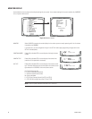
MAIN MENU
1
2
3
4
5
6
7
8
9
10
11
12
13
14
15
CAMERA
LOGICAL CAMERA
MONITOR
ACCESS
TIME & DATE
PORT
PRIORITY
SEQUENCE
MACRO
ALARM CONTACTS
EVENT TIMER
SET AUXILIARY
SET PASSWORD
SYSTEM
ABOUT CM6800E
ENGLISH
RETURN
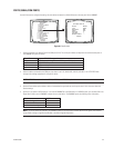
CAMERA 0001
VERTICAL DRIVE:
CONTROL:
PORT ADDRESS:
CAMERA TITLE
CAM 1
SELECT CHARACTER
RETURN
OFF
EXT COAX
01
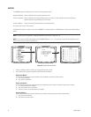
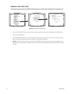
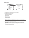
Figure 40. Program Cameras
1. In the CAMERA field, select the logical camera number of the video input to be defined.
2. In the CONTROL field, select the receiver control type.
EXT COAX: Coaxitron extended mode (32-bit)
STD COAX: Coaxitron standard mode (15-bit)
MUX: Genex multiplexer
PTZ-A: RS-422 Control Port A
PTZ-B: RS-422 Control Port B
M-02: Reserved for future use
M-08: Reserved for future use
NOTE: If you select PTZ-A or PTZ-B you must also program Serial Port 9 or 10 (refer to
Ports
in this section). A 96 x 16 System
includes PTZ-C and PTZ-D (Serial Ports 11 and 12).
3. The PORT ADDRESS field is required for Genex or RS-422 control only.
Genex multiplexer: Select the address of the multiplexer (01-32); this address must match the unit ID specified through
multiplexer programming. Refer to the MX4000 Genex Series Simplex and Duplex Multiplexers Installation/Operation Manual.
RS-422 cameras: Select the camera/device address for RS-422 control (01-32). The port address must match the address setting
configured through the camera/receiver DIP switch settings.
PROGRAM CAMERAS


