


153
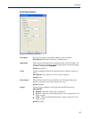
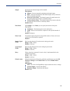
Channels
Functionality
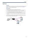
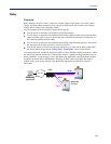
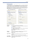
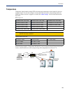
The Digital I/O extension feature requires the digital input to be connected to one or more digital
outputs/relays (local or on another IOLAN model), output serial signal pins, and/or TCP/IP
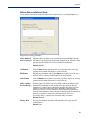
applications. In order to create a successful connection between the input and output or application,
one side must be must be set to
Listen for connection and the other side must be set to Connect to.
When the state of an input channel changes, a message is sent to all sessions currently associated with
that channel.
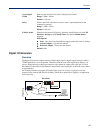
When the IOLAN is communicating to an application, there is no need for the output channel or
application to respond to messages from the input channel. Each input channel is reported
individually, so the receiving application gets the status only at the point at which the channel state
has changed.
The message format (from input channel to output channel/application) consists of 20 bytes per
status; 10 bytes are currently used and 10 are being reserved for future use.
Message Type
(1 Byte)
Input Number
(1 Byte)
IOLAN MAC
Address (6 Bytes)
Current Alarm
State (1 Byte)
Current Status
of Input (1 Byte)
Reserved
(10 Bytes)
z Message type: (1 Byte)
z 0 = Digital input status
z 1 = Serial I/O status
z Input number: (1 Byte)
z Digital input will be 1, 2, 3, or 4 to represent the channel number
z Serial I/O will be 5 = DSR, 6 = DCD, or 7 = CTS
z MAC Address of the IOLAN sending the input information. (6 Bytes)
z Current Alarm State: (1 Byte)
z 0 = Not in alarm
z 1 = In Alarm
z Current Status of Input: (1 Byte)
z 0 = Inactive for digital input.
z 1 = Active for digital input.
z Reserved for future use. Reserved bytes will have the value 0x00. (10 Bytes)
Applications should be written in such a way so that they look at the Message type byte to determine
the format of the message. If the application encounters a Message type it does not recognize, it
should discard the message and read the next 20 byte block.