


I/O Wiring Diagrams 219
Wiring I/O Diagrams
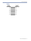
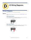
Analog Input
Make sure the Analog jumpers support the software setting; see Analog Input Module for jumper
settings.
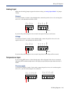
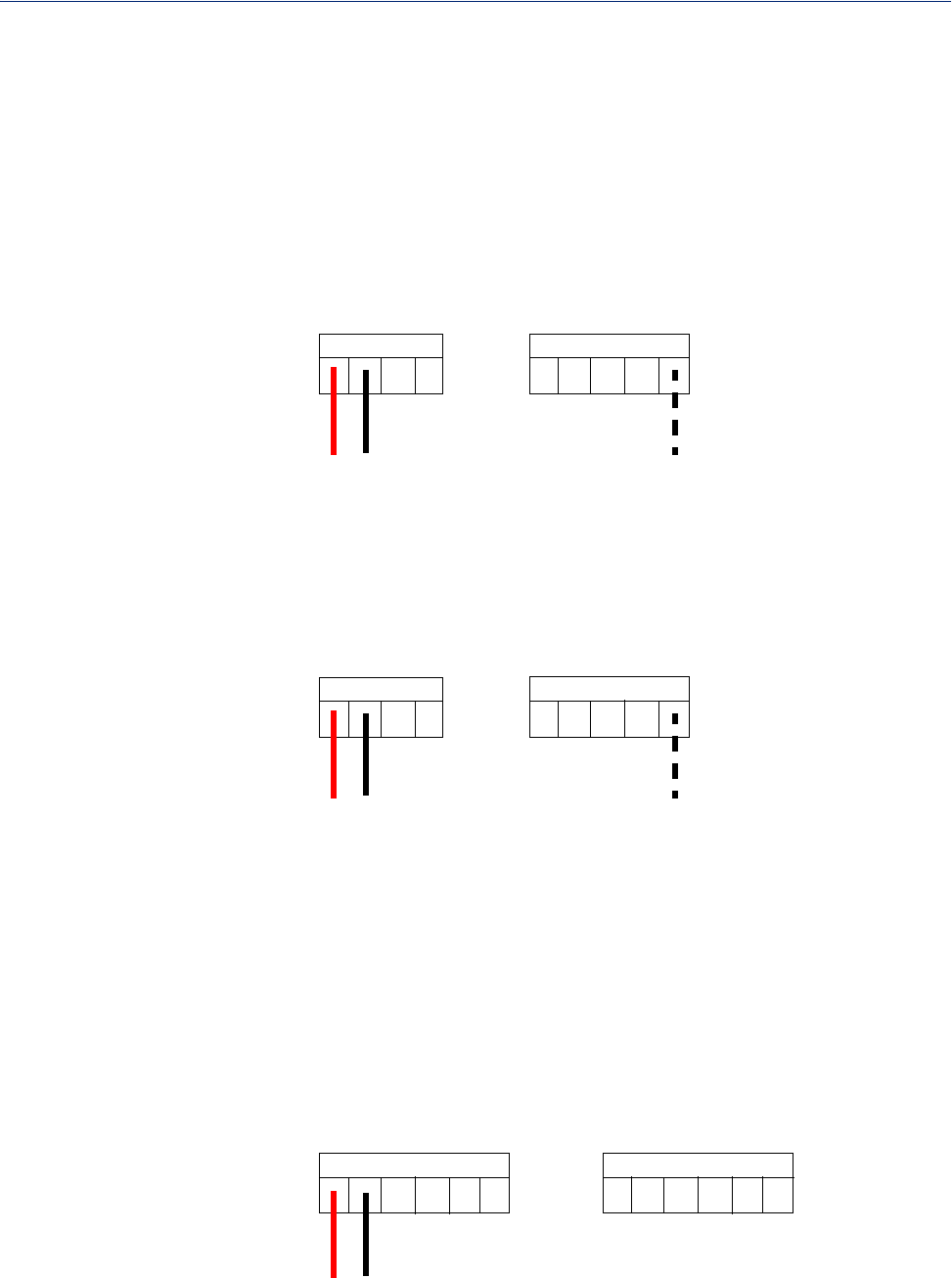
Current
To connect channel A1 with a 2-wire shielded cable, connect the positive wire to A1+, the negative
wire to A1-, and optionally the shield to GND.
A3+
A3-
A4+
A4-
GND
A1+
A1-
A2+
A2-
+
-
shield
If you have the positive/negative wires reversed, the output will always read 0 (zero).
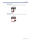
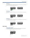
Voltage
To connect to Channel A1 with a 2-wire shielded cable, connect the positive wire to A1+, the
negative wire to A1-, and optionally the shield to GND.
A3+
A3-
A4+
A4-
GND
A1+
A1-
A2+
A2-
+
-
shield
If you have the positive/negative wires reversed, the polarity of the voltage will be reversed.
Temperature Input
If you are using RTD sensors, a short detected status will be displayed if the wires are connected
improperly. RTD or thermocouple sensors will display an open detection status when the circuit is
broken.
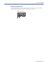
Thermocouple
To connect to Channel A1 with a 2-wire cable, connect the positive wire to A1+ and the negative
wire to A1-; you will not be using the A1s connection.
A1+
A1-
A1s
A2s
A2+
A2-
A3+
A3-
A3s
A4s
A4+
A4-
+
-