


175
Accessing I/O Data Via TruePort
Example 1: Read the status of the first digital input (DI1) on a D2R2 unit.
DI1 sensor is a coil register with the decimal value of 6145 (hex 0x1801).
Request: 0x01 0x18 0x01 0x00 0x01
Response: 0x01 0x01 0x01 (Digital input 1 is active)
Example 2: Read the values for the Inactive Signal Width, Active Signal Width, and Pulse
count for the second digital output (DO2) on a D4 unit.
DO2, Inactive Signal Width is a holding register with the decimal value of 6210 (hex 0x1842).
Request: 0x03 0x18 0x42 0x00 0x03
Response: 0x03 0x06 0x00 0x0A 0x00 0x11 0x00 0x0F
(Inactive =10*100ms, Active= 17*100ms, and Pulse count = 15)
Example 3: Read the raw current, minimum and maximum values of the third Analog input
(A3) on an A4D2 unit.
A3 current raw value is an input register with the decimal value of 2150 (hex 0x0866).
Request: 0x04 0x08 0x86 0x00 0x03
Response: 0x04 0x06 0x10 0x03 0x0F 0x30 0x10 0x20
(Current = 0x1003, Minimum = 0x0F30, and Maximum = 0x1020)
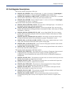
Set Commands
The following tables show the general structure to be used for set commands.
Note:
Numeric values provided in the API documentation are in Hexadecimal (Hex) format.
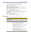
Command Format
Byte(s) # of Bytes Value
1 1 Command Code (in hex):
z 0x0F – Set “Boolean registers” (R/W coils)
z 0x10 – Set “holding registers” (read/write registers)
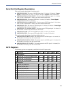
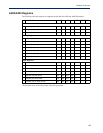
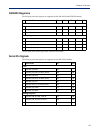
2-3 2 Starting register number (see A4/T4 Registers , A4D2/A4R2 Registers ,
or D4/D2R2 Registers for this value).
4-5 2 Number of registers to set. If this value is greater than 1, the response
will contain the values of multiple consecutive registers.
6 1 The length of the data (in bytes) to be written to the registers.
7-n n Data to be written to the registers.
If accessing registers which are 2 or 4 bytes, the data is in Network
order (Big endian) format (that is, MSB, LSB).
For Boolean registers, the value field will be a bit field with the LSBit
corresponding to the IO channel referenced by the starting register.