


I/O Wiring Diagrams 220
Wiring I/O Diagrams
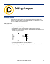
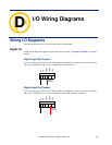
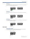
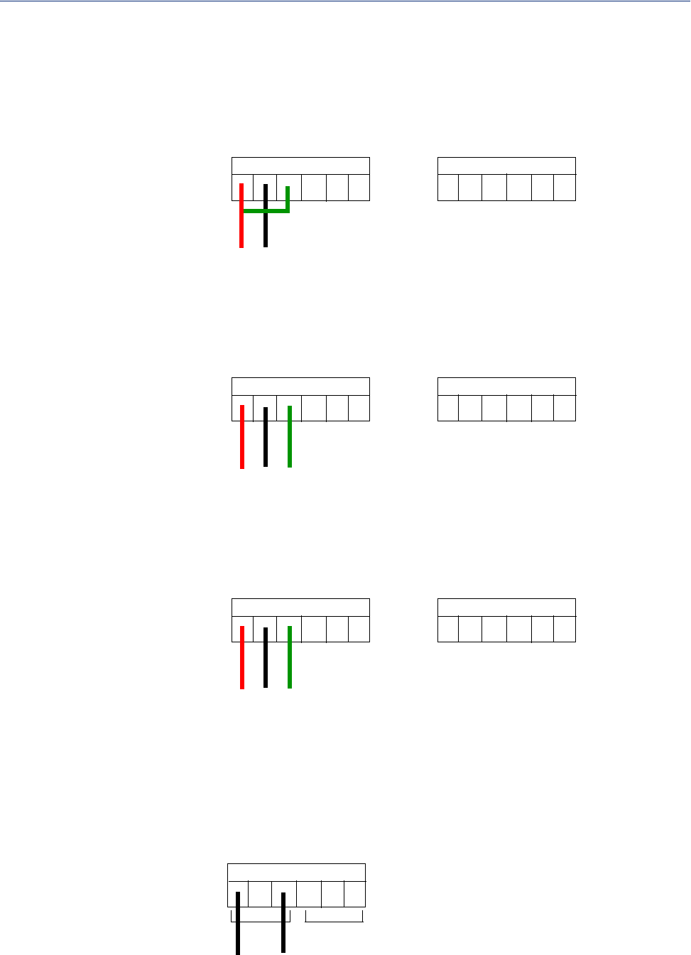
RTD 2-Wire
In a 2-wire RTD configuration, connect the excite wire to A1-, the return wire to A1+, and jumper the
sense wire from A1s with a insulated wire going to A1+.
A1+
A1-
A1s
A2s
A2+
A2-
A3+
A3-
A3s
A4s
A4+
A4-
return
excite
sense
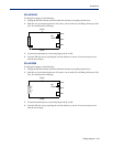
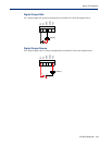
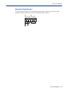
RTD 3-Wire
In a 3-wire RTD configuration, connect the return wire to A1+, the excite wire to A1-, and the sense
wire to A1s.
A1+
A1-
A1s
A2s
A2+
A2-
A3+
A3-
A3s
A4s
A4+
A4-
return
excite
sense
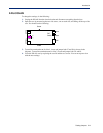
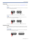
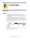
RTD 4-Wire
In a 4-wire RTD configuration, connect the return wire to A1+, the excite wire to A1-, the sense wire
to A1s, and leave the fourth wire disconnected.
A1+
A1-
A1s
A2s
A2+
A2-
A3+
A3-
A3s
A4s
A4+
A4-
return
excite
sense
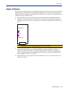
Relay Output
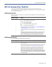
Normally Open Contact
To connect Relay channel R1 for a circuit that is normally inactive, connect one wire to the COM
(common) connector and one wire to the NO (normally open) connector.
COM
NC
NO
NO
COM
NC
R1
R2