


176
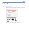
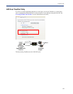
Accessing I/O Data Via TruePort
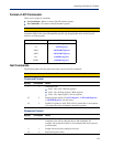
Successful Response Format
Byte(s) # of Bytes Value
1 1 Command code (from request).
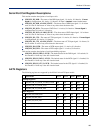
2 2 Starting register number (see A4/T4 Registers , A4D2/A4R2 Registers ,
or D4/D2R2 Registers for this value) from request.
4 2 Number of registers written.
Unsuccessful Response Format
Byte(s) # of Bytes Value
1 1 Command that this is a response to. If an error has been detected, the
command value will have the high bit set (OR with 0x80). For
example: The Command is 0x10, so the command field in the response
would be 0x90.
1 1 Error code, see Error Codes .
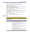
Example 1: Turn on the first relay on a D2R2 unit.
The first relay (R1) is a digital out coil register with a decimal value of 6659 (hex 0x1A03).
Request: 0x0F 0x1A 0x03 0x00 0x01 0x01 0x01
Response: 0x0F 0x1A 0x03 0x00 0x01
Example 2: Turn on the first and second relay on a D2R2 unit.
The first relay (R1) is a digital out coil register with a decimal value of 6659 (hex 0x1A03).
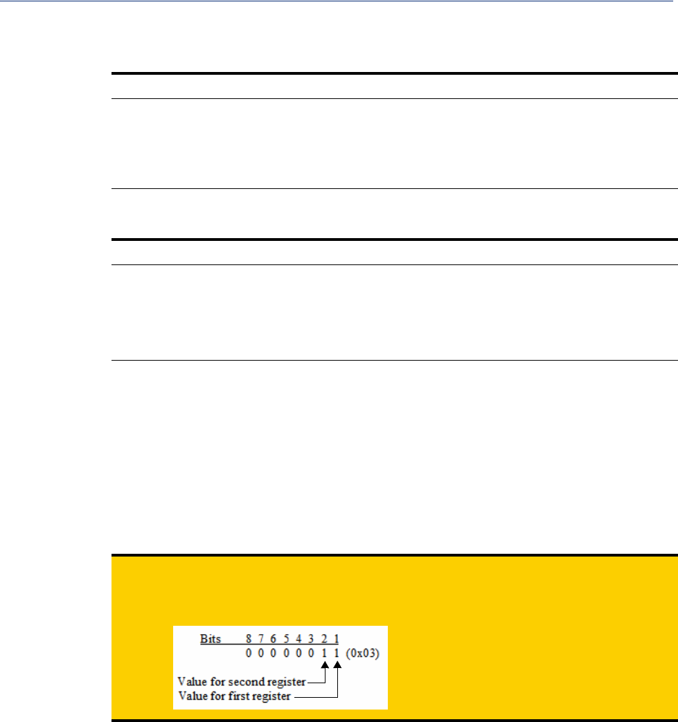
Request: 0x0F 0x1A 0x03 0x00 0x02 0x01 0x03 (03 = “00000011” which sets R1 and R2 to 1)
Response: 0x0F 0x1A 0x03 0x00 0x02
Note:
When reading or writing consecutive “Boolean” (coils) registers, the values of the registers
are combined into a single byte as shown by the example above. Two registers (coils) are
being written but the length of the data is 1 byte. The one byte contains the value for both
registers as follows: