


9
En
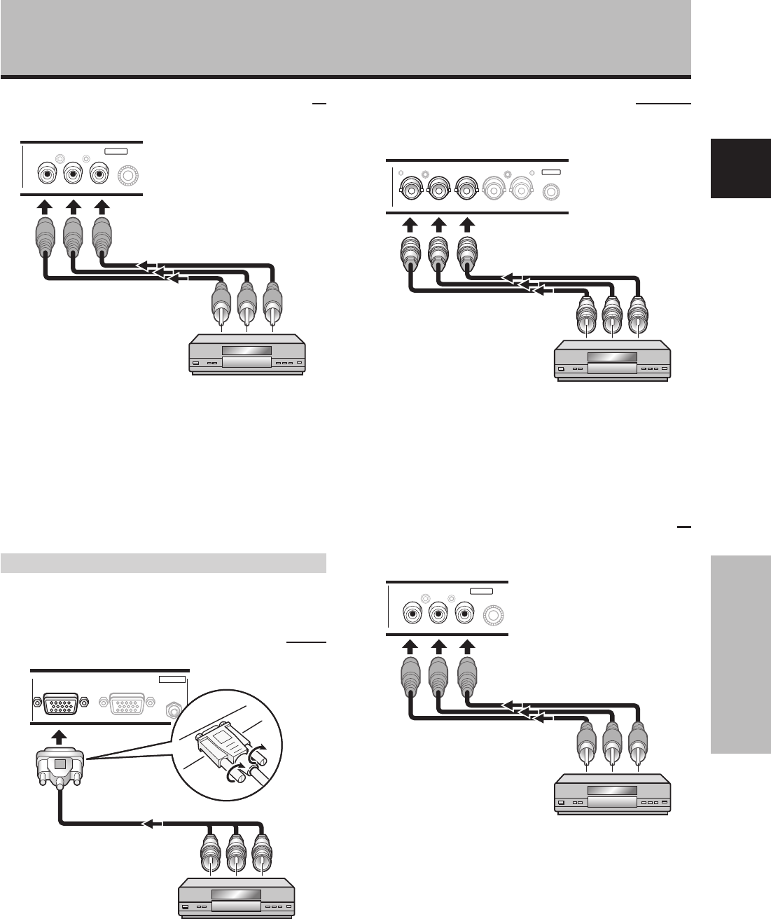
Installation and Connections
English
Installation and Connections
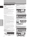
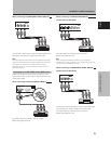
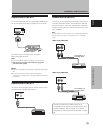
When connecting to COMPONENT VIDEO (INPUT5)
Y Pb/Cb Pr/Cr
INPUT5
COMPONENT
VIDEO
Connect the Y signal to the Y jack, the PB/CB signal to the
Pb/Cb jack, and the P
R/CR signal to the Pr/Cr jack.
Note
The plasma display and this Video Card are designed to support
component video signals with standard, stable signal levels and
sync signals. As a result, some image disruption may be
generated during use of various special trick play functions on
video components.
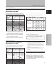
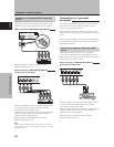
Connection of G ON SYNC analog RGB source
Make G ON SYNC connections for a component with
output that has the synchronization signal layered on top
of the green signal.
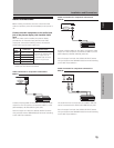
When connecting to ANALOG RGB IN (INPUT1)
ANALOG RGB IN
D-Sub
ANALOG RGB OUT
D-Sub
AUDIO
IN
INPUT1
On-screen setup is necessary after connection.
Please see pages 18 to 20.
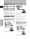
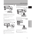
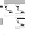
When connecting to ANALOG RGB (INPUT5)
[Connections for PDA-5003]
BR VDHD (H/V SYNC)G(ON SYNC)
ANALOG RGB
INPUT5
On-screen setup is necessary after connection.
Please see pages 18 to 20.
Note
When making G ON SYNC connections, do not make any
connections to the VD or HD jacks. If connections are made, the
picture may be not displayed normally.
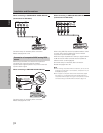
When connecting to COMPONENT VIDEO (INPUT5)
[Connections for PDA-5004]
Y Pb/Cb Pr/Cr
INPUT5
COMPONENT
VIDEO
Connect the G ON SYNC signal to the Y jack, the B signal
to the Pb/Cb jack, and the R signal to the Pr/Cr jack.
On-screen setup is necessary after connection.
Please see pages 18 to 20.