


12
En
English
Installation and Connections
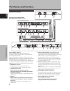
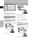
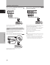
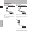
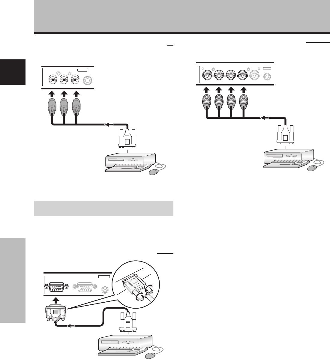
When connecting to COMPONENT VIDEO (INPUT5)
[Connections for PDA-5004]
Y Pb/Cb Pr/Cr
INPUT5
COMPONENT
VIDEO
On-screen setup is necessary after connection.
Please see pages 18 to 20.
Connection of composite SYNC analog RGB
source
Make composite SYNC connections for a personal
computer with output that has the vertical
synchronization signal layered on top of the horizontal
synchronization signal.
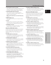
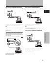
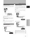
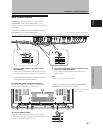
When connecting to ANALOG RGB IN (INPUT1)
ANALOG RGB IN
D-Sub
ANALOG RGB OUT
D-Sub
AUDIO
INPUT1
On-screen setup is necessary after connection.
Please see pages 18 to 20.
Installation and Connections
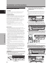
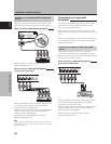
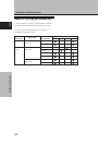
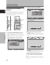
When connecting to ANALOG RGB (INPUT5)
[Connections for PDA-5003]
BR VD
HD (H/V SYNC)
G(ON SYNC)
ANALOG RGB
INPUT5
When using INPUT5, set the impedance selector switch
to match the output impedance of the connected
computer’s synchronization signal.
When the output impedance of the sync signal is below
75 Ω remove the video card and set the impedance
selector switch to 75 Ω (page 6).
On-screen setup is necessary after connection.
Please see pages 18 to 20.
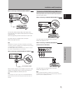
Notes
÷ When making composite SYNC connections, do not connect
anything to the VD jack. If connected to, the picture may not
be displayed properly.
÷ Some types of computer devices manufactured by Apple
Computer, Inc. are equipped with both G ON SYNC and
composite SYNC outputs. This type of component should be
connected using the G ON SYNC connection (page 11).