


11
En
Installation and Connections
English
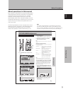
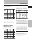
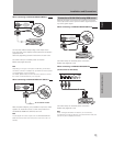
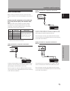
When connecting to ANALOG RGB IN (INPUT1)
ANALOG RGB IN
D-Sub
ANALOG RGB OUT
D-Sub
AUDIO
INPUT1
Connect the cable corresponding to the shape of the
input terminal on the display and the personal computer’s
output terminal.
Secure by tightening the terminal screws on both units.
On-screen setup is necessary after connection.
Please see pages 18 to 20.
Note
Depending on the type of computer model being connected, a
conversion connector or adapter etc. provided with the computer
or sold separately may be necessary.
For details, please read your PC’s instruction manual or consult
the maker or nearest dealer of your computer.
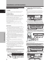
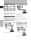
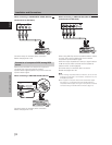
When connecting to ANALOG RGB OUT (INPUT1)
ANALOG RGB IN
D-Sub
ANALOG RGB OUT
D-Sub
AUDIO
INPUT1
With the plasma display, it is possible to output the video
signal to an external monitor or other component from
the ANALOG RGB OUT (INPUT1) terminal.
Note
A video signal will not be output from the ANALOG RGB OUT
(INPUT1) terminal when the main power of this unit is off or in
standby.
To an external monitor
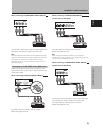
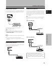
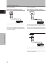
Connection of G ON SYNC analog RGB source
Make G ON SYNC connections for a personal computer
with output that has the synchronization signal layered on
top of the green signal.
When connecting to ANALOG RGB IN (INPUT1)
ANALOG RGB IN
D-Sub
ANALOG RGB OUT
D-Sub
AUDIO
INPUT1
On-screen setup is necessary after connection.
Please see pages 18 to 20.
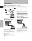
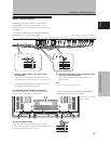
When connecting to ANALOG RGB (INPUT5)
[Connections for PDA-5003]
BR VD
HD (H/V SYNC)
G(ON SYNC)
ANALOG RGB
INPUT5
On-screen setup is necessary after connection.
Please see pages 18 to 20.
Note
When making G ON SYNC connections, do not make any
connections to the VD or HD jacks. If connections are made, the
picture may be not displayed normally.
Installation and Connections