20
En
English
System Settings
System Settings
[CLAMP POSITION] setup
Depending on the signal, analog RGB signals may result
in the screen image appearing with a whitish or greenish
cast. In such cases, set [CLAMP POSITION] to [LOCKED].
Normally, leave this setting at [AUTO].
1
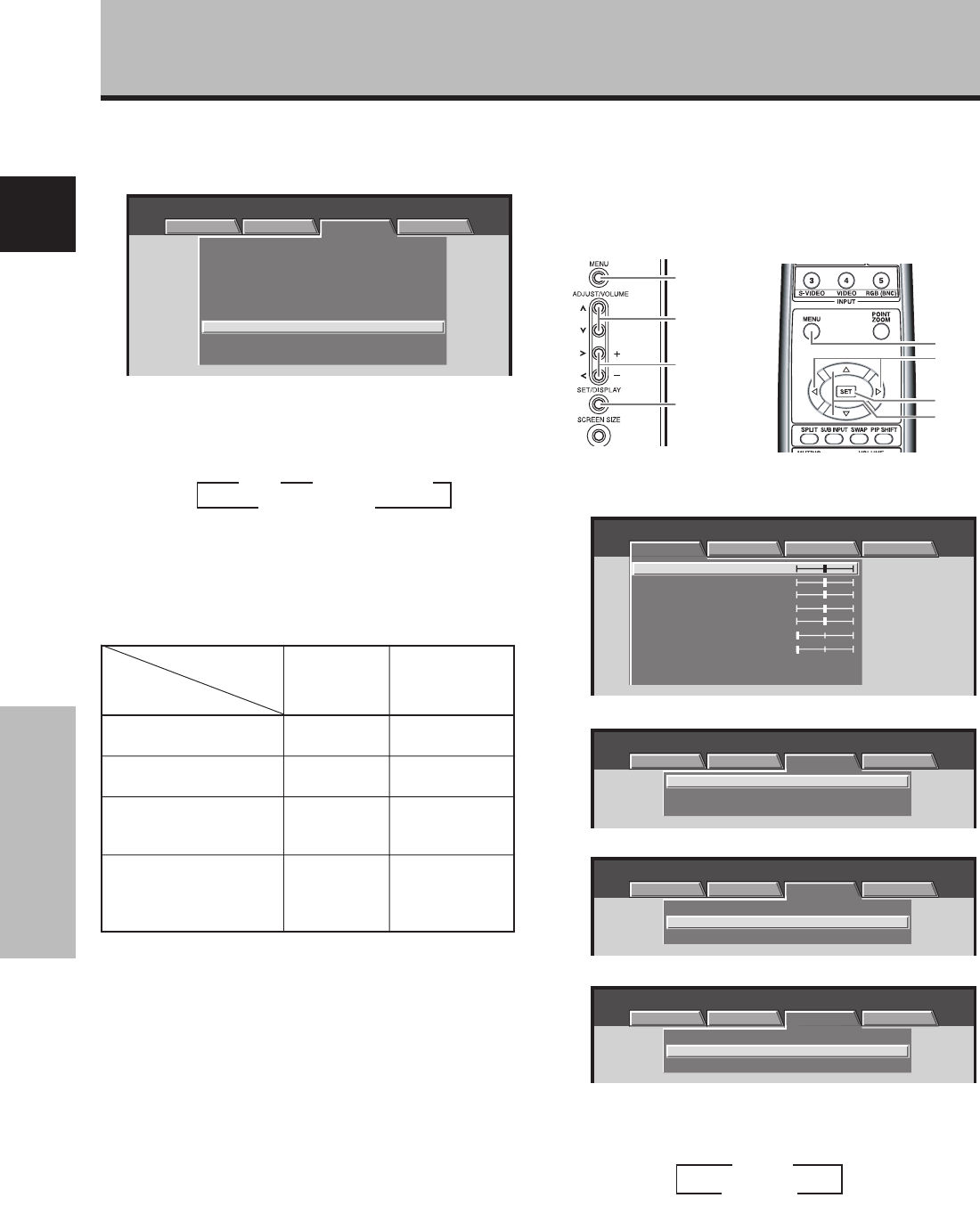
Press the MENU button to display the menu screen.
MENU INPUT1
PICTURE SCREEN SETUP OPTION
:
0
:
0
:
0
:
0
:
0
:
0
CONTRAST
:
0
BRIGHTNESS
R.LEVEL
G.LEVEL
B.LEVEL
H.ENHANCE
V.ENHANCE
PICTURE RESET
2 Use the 2/3 buttons to select [SETUP].
:
V
GA
:
:
SIGNAL FORMAT
CLAMP POSITION
:
AUTO
POWER MANAGEMENT
OFF
MENU INPUT1
PICTURE SCREEN SETUP OPTION
3
Use the 5/∞ buttons to select [CLAMP POSITION].
V
GA
:
:
SIGNAL FORMAT
CLAMP POSITION
:
AUTO
POWER MANAGEMENT
OFF
MENU INPUT1
PICTURE SCREEN SETUP OPTION
4 Press the SET button to select [LOCKED].
V
GA
:
:
SIGNAL FORMAT
CLAMP POSITION
:
LOCKED
POWER MANAGEMENT
OFF
MENU INPUT1
PICTURE SCREEN SETUP OPTION
The factory default setting is [AUTO].
Mode selection will change as follows each time the
SET button is pressed:
5 When the setup is completed, press the MENU
button to exit the menu screen.
Notes
÷ Make this [CLAMP POSITION] setting for each applicable input
(PDA-5003: INPUT1 or INPUT5, PDA-5004: INPUT1).
÷ When using this setup, be sure to carefully check the signal
output of the component that you are using. For details, please
refer to the instruction manual supplied with the component
you are connecting.
3 AUTO
LOCKED 2
The table below shows what settings are appropriate
and available for the type of connections made.
Set [SIGNAL FORMAT] and [COLOR DECODING] as follows.
Please take care when making settings. Incorrect settings
can adversely affect the plasma display.
9 When the setup is completed, press MENU to exit
the menu screen.
Notes
÷ Make this [SIGNAL FORAMT] setting for each applicable input
(INPUT1, INPUT2 or INPUT5).
÷ Make [COLOR DECODING] settings individually for INPUT 1 or
INPUT 5.
÷ The [COLOR DECODING] setting is not supported when
inputting a computer signal, or when the [SIGNAL FORMAT]
function has been used to select a signal other than [525p] or
[750p].
7 When a component other than a computer is
connected, use the 5/∞ buttons to select [COLOR
DECODING] (INPUT1 or INPUT5).
MENU INPUT1
PICTURE SCREEN SETUP OPTION
:
:
:
DNR
COLOR TEMP.
:
MIDDLE
MIDDLE
:
MPEG NR LOW
:
CTI ON
:
PURECINEMA
OFF
:
:
:
SIGNAL FORMAT
COLOR DECODING
RGB
VGA
:
CLAMP POSITION
AUTO
AUTO POWER OFF
DISABLE
8 Press the SET button repeatedly to select the
input signal format.
Selection will change as follows each time the SET
button is pressed:
3
RGB
COMPONENT22
3
COMPONENT1
Component video output
of a DVD player, etc.
Component video output
from digital tuner, etc.
RGB video output of a
video deck etc., with RGB
output
RGB video output of a PC
Connected
component
COLOR
DECODING
SIGNAL
FORMAT
SETUP
525p
750p
525p
VGA, WVGA,
720-PC,
XGA, WXGA,
SXGA, SXGA+
COMPONENT1
COMPONENT2
RGB
Not supported
MENU
2/3
5/∞
SET
MENU
5/∞
SET
2/3
Display operating panel Remote control unit


