


6
En
English
Installation and Connections
Installation and Connections
Installing the video card
TO USERS:
This component is sold with the understanding that it will be
installed by a specialist possessing appropriate technical
knowledge and ability.
TO SALES AGENTS:
Installation instructions are noted below. When installing the unit,
if a screw or other object should drop inside the plasma display,
immediately consult your nearest Pioneer Service Center.
Continuing operation may result in malfunction.
This device has been designed for installation on the Pioneer
Plasma Display PDP-504CMX/PDP-50MXE1/PDP-50MXE1-S or
PDP-434CMX/PDP-43MXE1/PDP-43MXE1-S. Installation
procedures are as follows:
Confirm the following before installing this video card:
• Disconnect the plasma display from computer or other
components.
• Disconnect the plasma display’s power cord from its outlet.
Installation Notes:
÷ When opening the protective cover, take care not to drop
screws or other objects in the opening. Objects dropped inside
the display may cause damage or malfunction.
÷ When installing the video card, if the plasma display is laid
with its screen side facing down, the work surface should be
flat and level, and either the packing material, a blanket, or
other soft material should be spread on the work surface first
to protect the screen. Take care to prevent scratches or other
damage to the unit from tools or other objects. Never rest the
display on a surface in such a way that weight or pressure is
placed only on the screen surface.
÷ This video card has been designed for exclusive use with the
Pioneer Plasma Display PDP-504CMX/PDP-50MXE1/PDP-
50MXE1-S or PDP-434CMX/PDP-43MXE1/PDP-43MXE1-S. Do
not attempt unauthorized modifications or alterations since
malfunction or damage may result.
÷ Take care not to modify or damage the card’s internal devices
in any way.
÷ Before installation, take precautions to eliminate static
electricity on your body. Do not touch the card’s circuitry or
devices.
÷ This device has not been designed to allow reinstallation or
removal; after the card has once been installed on the plasma
display, do not attempt to remove it since damage may result.
÷ When installing the PDA-5003, it may be necessary to adjust
the setting of the impedance selector switch. Confirm this
item before installing (pages 10, 12).
÷ Do not install the PDA-5002 on the PDP-504CMX/PDP-
50MXE1/PDP-50MXE1-S or PDP-434CMX/PDP-43MXE1/PDP-
43MXE1-S display units.
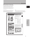
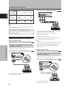
Installation
Illustration depicts PDA-5003 model.
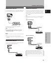
1 Remove the protective cover over the video card
slot on the plasma display’s terminal panel.
2 Insert the video card gently and evenly in
alignment with the two rails visible inside the
installation port.
Notes
÷ Be very careful when inserting the card. Install the card’s
device mounting surface oriented toward the rear side of the
plasma display. Insert straight! The card or display may be
damaged if the card is inserted crooked or with excessive
force.
÷ Impedance selector switch is found on PDA-5003 only.
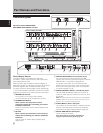
AUDIO
INPUT5
INPUT 3/4
AUDIO
VIDEO
ANALOG RGB
HD (H/V SYNC)
S-VIDEO INPUT3
INPUT4
3
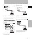
After inserting the video card all the way into the
slot, confirm that it is seated securely, then use the
screws removed in step 1 to secure the card in place.
AUDIO
INPUT5
INPUT 3/4
AUDIO
VIDEO
ANALOG RGB
HD (H/V SYNC)
S-VIDEO INPUT3
INPUT4
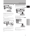
4 Affix the accessory connector indicator label to the
plasma display, and affix the remote control unit
label to the remote control unit furnished with the
plasma display.
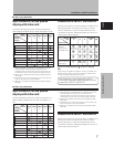
RGB (BNC)
COMPONENT
PDA-5003
PDA-5004
AUDIO
INPUT5
INPUT 3/4
AUDIO
VIDEO
ANALOG RGB
HD (H/V SYNC)
S-VIDEO INPUT3
INPUT4
INPUT3
S-VIDEO
VIDEO INPUT3
/
4 ANALOG RGB AUDIO
(ON SYNC) (H/V SYNC)
IN OUT R L RLGBRHDVD
INPUT4 INPUT5AUDIO
Note
Use a soft cloth to gently wipe away any dust or soiling from the
surface before affixing the label.
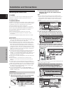
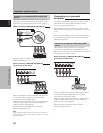
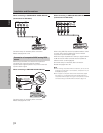
Video Card Removal (In principle, removal of
the video card should not be attempted).
1 Remove the two screws holding the video card.
AUDIO
INPUT5
INPUT 3/4
AUDIO
VIDEO
ANALOG RGB
HD (H/V SYNC)
S-VIDEO INPUT3
INPUT4
2 Holding the inside tabs, pull the video card out
straight.
AUDIO
INPUT5
INPUT 3/4
AUDIO
VIDEO
ANALOG RGB
HD (H/V SYNC)
S-VIDEO INPUT3
INPUT4
Protective cover
Impedance
selector switch
75 Ω 2.2 kΩ
Impedance
selector switch
75Ω 2.2kΩ
Device
mounting
surface
Device
mounting
surface